Automatic fiber placing device for placing fibrous composite material

A fiber composite material and automatic laying technology, which is applied in the field of automatic laying equipment, can solve the problems of inability to compaction, poor laying accuracy, and inability to apply prepreg by pressing rollers.

Pending Publication Date: 2018-08-21
BAODING BIAOZHENG MACHINE TOOL
View PDF13 Cites 16 Cited by
  • Summary
  • Abstract
  • Description
  • Claims
  • Application Information

AI Technical Summary

Problems solved by technology

However, the existing automatic wire laying equipment is widely used in the fields of aircraft, aerospace and military industry, and the technology is mainly controlled by European and American countries, which impose restrictions on the technology needs of our country; domestic technical personnel are also stepping up research, but only limited to some local technical improvements , for example, the patent number is 201210150630.8, and the name is the invention patent application of the method and equipment for automatically laying prepreg filaments, which solves the technical problem that the prepreg filaments cannot be compacted due to the tilting of the pressure roller when it meets the hemming; the patent number is 201710032960 .X, the name is a kind of process equipment for fiber winding layup. In order to solve the problem that the existing fiber reinforced materials are difficult to process, a fixed outer ring, an inner disc that rotates freely in the outer ring, and a positioning in the inner disc are studied. A device consisting of a sleeve in a hole
However, due to the lack of cooperation with other technologies, it cannot be applied in practice, and whether it can be realized in practical applications is also a problem.
At present, there is no complete automatic laying equipment for fiber composite materials in China, and foreign countries have been embargoing such equipment in China, and have imposed a technical blockade. Therefore, the laying of fiber composite materials in China is manually processed and laid. Poor, slow speed, low laying efficiency, unstable laying quality

Method used


Image

  • Automatic fiber placing device for placing fibrous composite material
  • Automatic fiber placing device for placing fibrous composite material
  • Automatic fiber placing device for placing fibrous composite material

Examples


Embodiment Construction

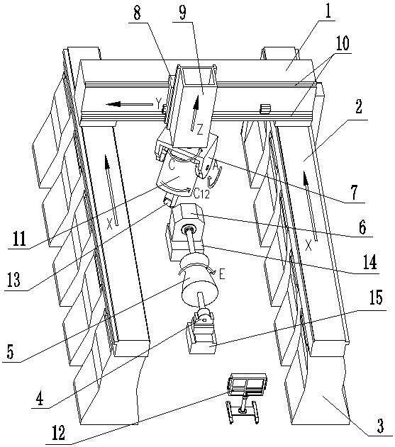
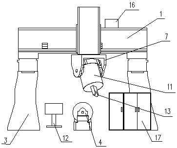
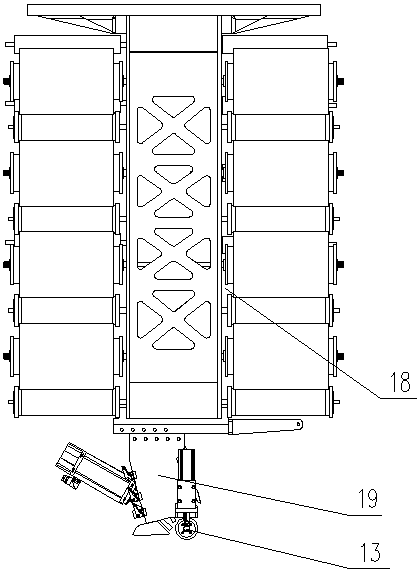
[0030] The present invention will be further described below in conjunction with the accompanying drawings and specific embodiments.

[0031] like figure 1 , figure 2 , image 3 , Figure 4 , Figure 5 , Image 6 , Figure 7 , Figure 8 , Figure 9 and Figure 10 As shown in and , this embodiment includes two columns 3 arranged symmetrically, two longitudinal beams 2 installed on the two columns 3, a transverse beam 1, a sliding seat 8, a ram 9, a rotary device 7, including a control servo motor A, a servo Motor B, servo motor C, servo motor D, C-axis rotary mechanism, C1-axis rotary mechanism, A-axis rotary mechanism and the operation control system of the brake device, the power control device of the infrared heating device, and each on the silk laying head device The control system of separate winding, tensioning, clamping, shearing and re-feeding control devices for filament bundles, including the creel 18, the laying head 19, the laying head pressure roller 13 a...


PUM


Abstract

The invention discloses an automatic fiber placing device for placing a fibrous composite material. Two servo motors A drive two output gears to be rotated along an X-directional long rack, so a crossbeam is driven to be slid along a longitudinal beam; a servo motor B drives a sliding base to be slid along the cross beam; a servo motor C drives a Z-directional screw rod to be rotated, so a ram isdriven to be upwards and downwards slid along the sliding base; a C-axis rotation mechanism fixed on a fixing body drives a C-axis rotation body to be rotated along a C-axis of a center shaft of theC-axis rotation body; an A-axis rotation mechanism drives a swinging body to be rotated along an A-axis of an axial lead of two coaxial shafts; a C1-axis rotation mechanism fixed on the swinging bodydrives a creel to be rotated along a C1-axis of a center shaft of the creel; a fiber placing head and a fiber placing head press roller are fixed at the lower end of the creel; a control system controls the C-axis, C1-axis and A-axis rotation mechanisms and a brake device to be operated; and a servo motor D drives a workpiece to be rotated along a rotation principal axis of the workpiece. The automatic fiber placing device is high in placement precision, rapid in speed, high in placement working efficiency, and stable in placement quality.

Description

technical field [0001] The invention relates to an automatic fiber laying equipment for laying fiber composite materials. Background technique [0002] Fiber composites are widely used in industries such as aircraft, aerospace, wind power and transportation. The current processing methods of fiber-reinforced composites are mainly hand lay-up, vacuum bag, molding and automatic silk laying process. Automatic wire laying technology is a key development technology in the fields of aircraft, aerospace, wind power and transportation in the future. However, the existing automatic wire laying equipment is widely used in the fields of aircraft, aerospace and military industry, and the technology is mainly controlled by European and American countries, which impose restrictions on the technology needs of our country; domestic technical personnel are also stepping up research, but only limited to some local technical improvements , for example, the patent number is 201210150630.8, an...

Claims


Application Information

Patent Timeline
Patent Type & Authority Applications(China)
IPC IPC(8): B29C70/38B29C70/54
CPCB29C70/384B29C70/54B29C70/56
Inventor 邝连杰支勉
Owner BAODING BIAOZHENG MACHINE TOOL
Why Eureka
Try Eureka