Electronic key storage box

An electronic key and driving circuit technology, applied in the field of key boxes, can solve the problems of inconvenient opening and official code setting, poor safety, manual opening, etc., and achieve the effect of compact and ingenious structure, strong resistance to external force knocking, and prevention of false opening.

Active Publication Date: 2018-08-21
SUZHOU JINLIN METAL
View PDF7 Cites 7 Cited by
  • Summary
  • Abstract
  • Description
  • Claims
  • Application Information

AI Technical Summary

Problems solved by technology

[0004] As mentioned above, on the one hand, the structure of the mechanical word wheel combination lock is relatively complicated, which makes it inconvenient to open and set the official code. On the other hand, after the password is correct, it still needs to be manually opened.
More importantly, the locks currently used in this type of key box are all locked by the cooperation of the lock tongue and the lock hole. The lock tongue uses the elastic force of a single spring as the locking force to support the closing of the lock tongue and the lock hole. After the vibration, it is inevitable that there will be a problem of false opening, and the safety is poor

Method used


Image

  • Electronic key storage box
  • Electronic key storage box
  • Electronic key storage box

Examples


Embodiment 1

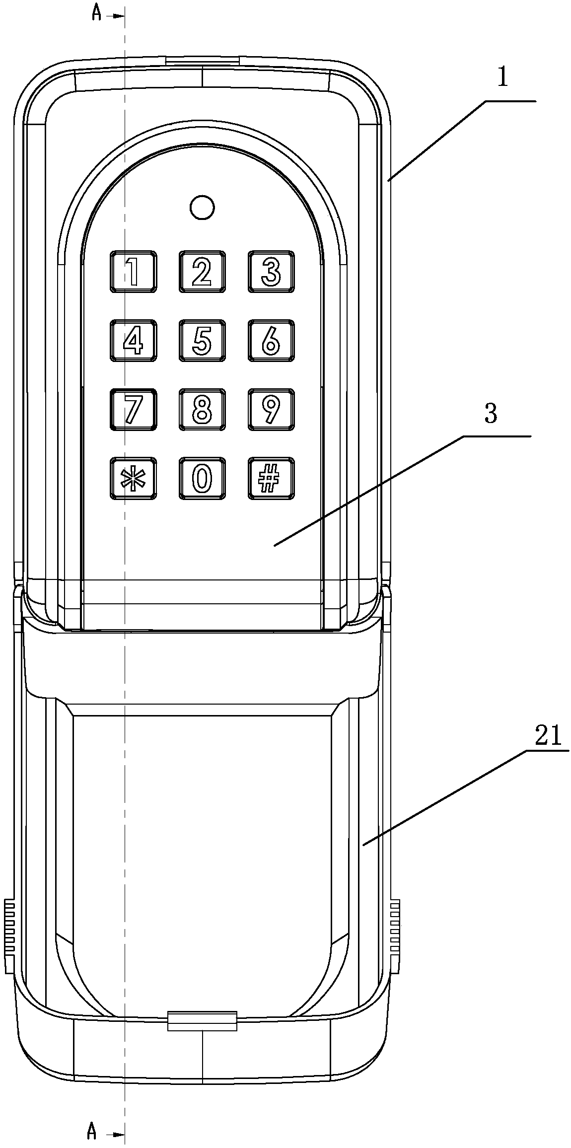
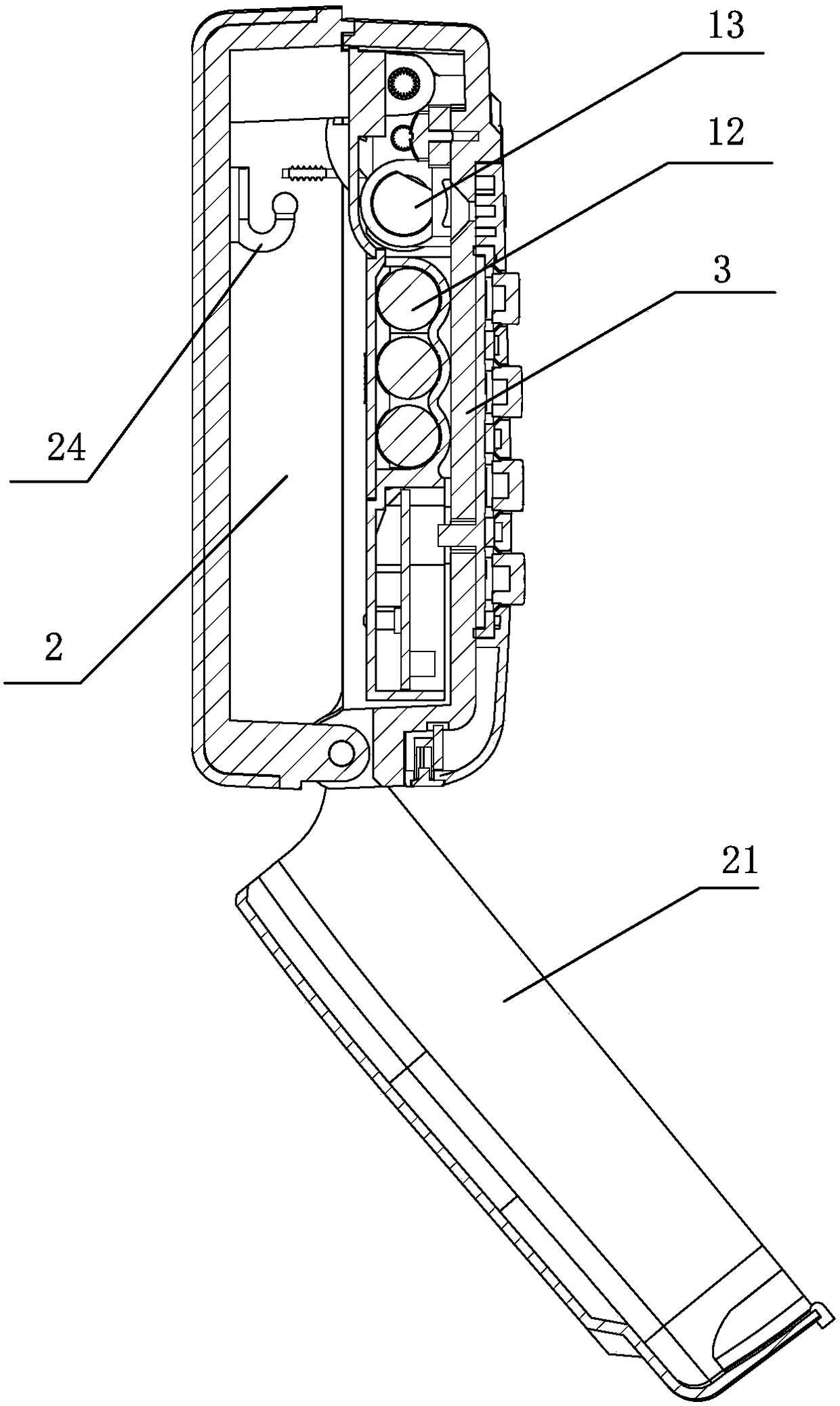
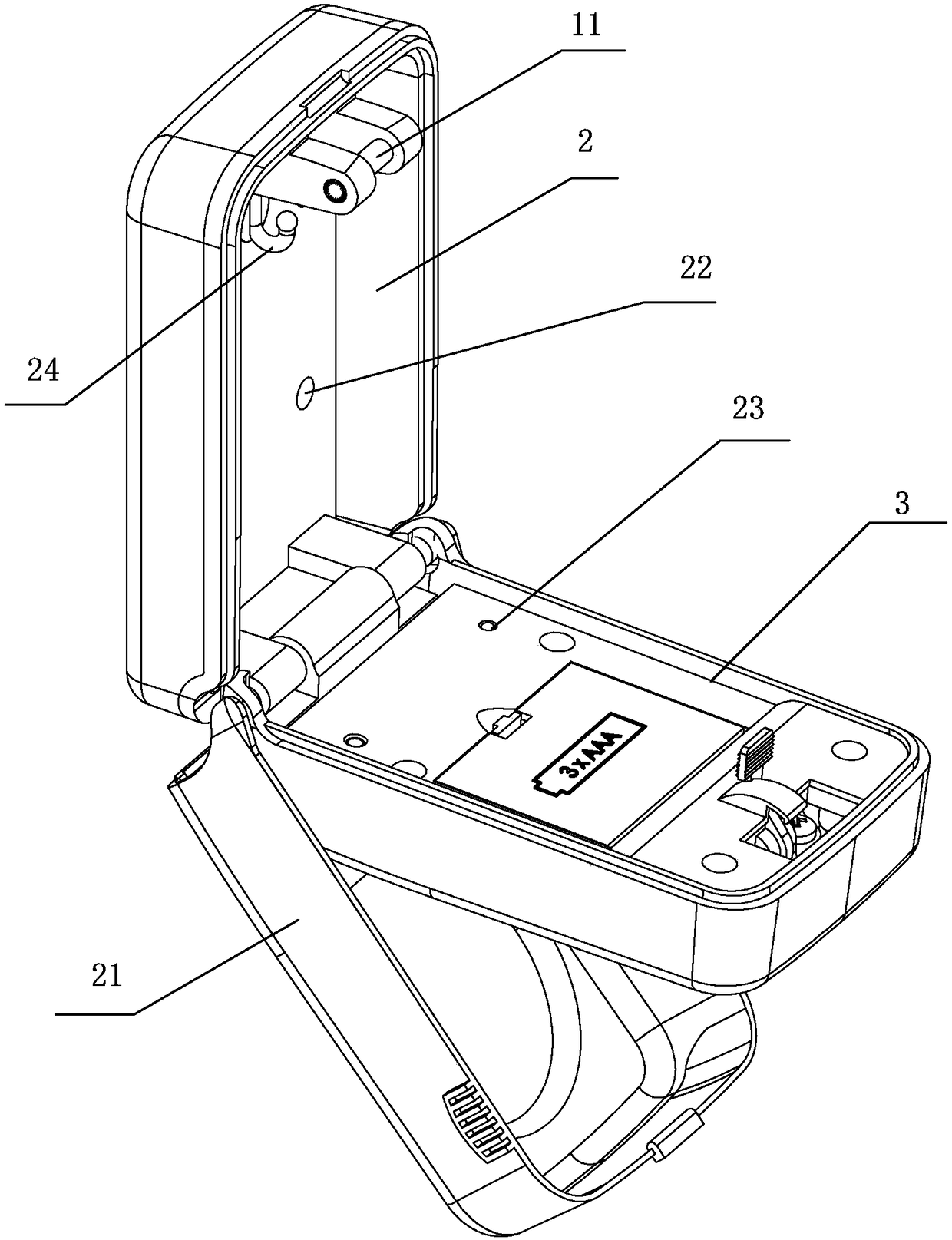
[0039] Embodiment one: see Figure 1-9 As shown, an electronic key storage box includes a housing 1, which is arranged in a cavity 2 for storage in the housing 1, and the front of the housing 1 is provided with a front panel 3 for password input. The inner side of the panel 3 is provided with a lock mechanism 4 and a control circuit, the lock mechanism 4 is an electronic lock, including a drive circuit, a deadbolt piece 5 and an installation assembly 6 connected to the deadbolt piece 5,

[0040] The drive circuit is used to receive the unlocking information from the control circuit, and control the action on the deadbolt piece 5;

[0041]The installation assembly 6 includes a lock bracket 7, a rotating shaft 8 positioned on the lock bracket 7 and a lock hook spring 9 disposed on the rotating shaft 8, the dead bolt sheet 5 is sleeved on the rotating shaft 8, and the lock hook spring The active end of 9 is connected to the lock tongue piece 5, and the lock tongue piece 5 is pro...

Embodiment 2

[0052] Embodiment two, see appendix Figure 10-11 As shown, an electronic key storage box includes a housing 1, which is arranged in a cavity 2 for storage in the housing 1, and the front of the housing 1 is provided with a front panel 3 for password input. The inner side of the panel 3 is provided with a lock mechanism and a control circuit, and the lock mechanism is an electronic lock, including a driving circuit, a deadbolt piece and an installation component connected with the deadbolt piece. In this embodiment, its structure is basically similar to that of Embodiment 1, the difference is that: the drive circuit can choose to use alternating current to control the positive and negative paths of the motor through the control circuit, so as to realize the positive and negative rotation of the main shaft , Therefore, in this embodiment, there is no need to use a return spring to reset the main shaft. This solution is not as simple in structure as the first embodiment, and th...


PUM


Abstract

The invention discloses an electronic key storage box which comprises a shell and a cavity formed inside the shell and used for storage. A front panel for password input is arranged at the front faceof the shell, and a lock mechanism and a control circuit are arranged on the inner side of the front panel. The electronic key storage box is characterized in that the lock mechanism is an electroniclock and comprises a driving circuit, a lock tongue piece and an installing assembly connected with the lock tongue piece, and the driving circuit is used for receiving unlocking information of the control circuit and controlling the effect on the lock tongue piece; the installing assembly comprises a lock support, a rotating shaft located on the lock support and a lock hook spring arranged on therotating shaft, a lock hook groove is formed in the lock tongue piece, and the lock hook groove is matched with a locking pin on the shell; the lock tongue piece is matched with the lock hook springthrough the driving circuit, so that the lock hook groove and the locking pin form the engaged state or the separated state. By adopting the mode of the electronic lock, a key box can be automaticallyopened, use is more convenient, the lock structure is safer, and error starting is avoided.

Description

technical field [0001] The invention relates to a key box, in particular to an electronic key storage box. Background technique [0002] A key box, as the name implies, is a box used to store keys. Generally speaking, when we go out, we are used to carrying a large number of door keys, including unit door, security door, garage door, letterbox door, etc. It is very inconvenient to carry them with us, and there is also the possibility of forgetting or losing them, so they are used for storage. The key box for keys came into being. [0003] Existing key boxes are mainly based on mechanical locks, such as the "key box combination lock" (CN104234528A) disclosed in the Chinese invention patent application, which includes a lock ring, a rear lock body, a front lock body, a rear lock gate group, and a lock gate seat And the lock head, the front lock body and the rear lock body are hinged, the front lock body and the rear lock body are closed to form a cavity for accommodating the...

Claims


Application Information

Patent Timeline
Patent Type & Authority Applications(China)
IPC IPC(8): E05B19/00E05B65/52E05B47/00E05B17/20A45C11/32
CPCA45C11/32E05B17/2084E05B19/0082E05B47/0012E05B65/52E05B47/0607E05C3/24E05B19/0005F21Y2115/10E05B49/00E05B67/063F21V23/0471
Inventor 刘钟陈海波
Owner SUZHOU JINLIN METAL
Why Eureka
Try Eureka