
Air-fuel ratio measurement system comprising optical sensor

A measurement system and optical sensor technology, applied in the field of measurement systems, can solve problems such as difficulty in optimizing system performance, and achieve the effect of small impact and optimized air-fuel ratio

Inactive Publication Date: 2018-08-21
KOREA INST OF IND TECH
View PDF7 Cites 2 Cited by
  • Summary
  • Abstract
  • Description
  • Claims
  • Application Information

AI Technical Summary

Problems solved by technology

[0006] That is, since the measurement technology related to the above uses a simple optical sensor and a camera, for the spatial resolution performance, in the case of a complex combustion flow, there is a problem that it is difficult to optimize the system performance as it has three-dimensional spatial resolution performance

Method used


Image

  • Air-fuel ratio measurement system comprising optical sensor
  • Air-fuel ratio measurement system comprising optical sensor
  • Air-fuel ratio measurement system comprising optical sensor

Examples


Embodiment Construction

[0033] The components constituting the air-fuel ratio measuring system including the optical sensor of the present invention can be used as a whole or separately as needed. Also, some components may be omitted in use depending on the usage form.

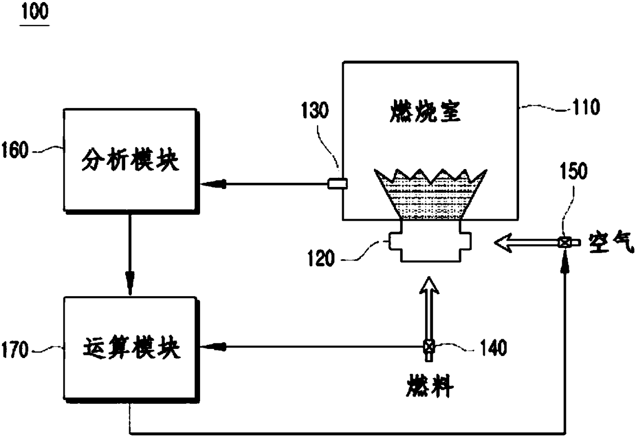
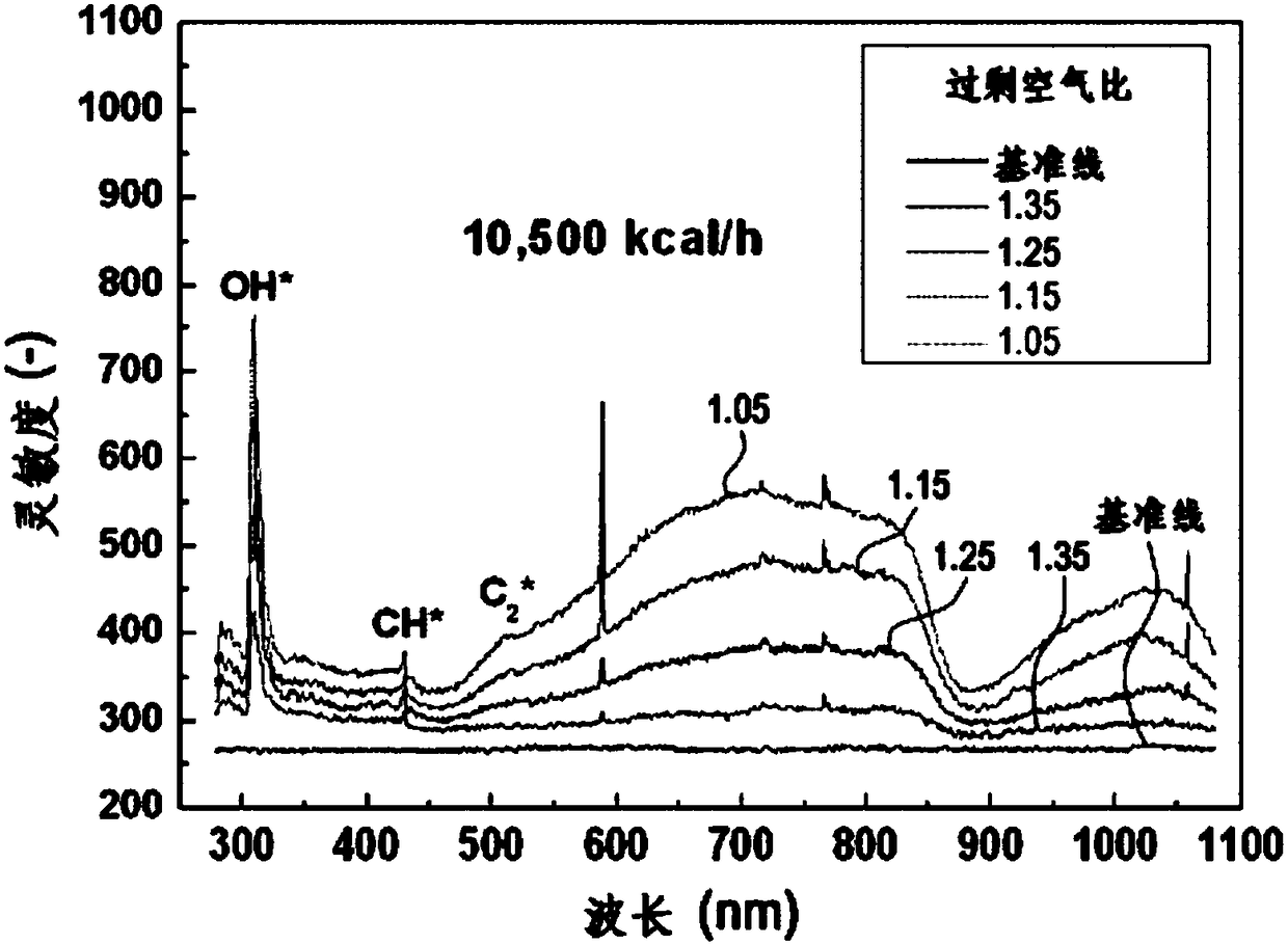
[0034] refer to Figure 1 to Figure 8 A preferred embodiment of the air-fuel ratio measurement system 100 including the optical sensor of the present invention is described. In this process, in order to make the description more clear and convenient, the thickness of the lines or the size of the components shown in the drawings may be exaggerated. In addition, terms described later are terms defined in consideration of functions in the present invention, and may be changed according to user's or operator's intention or custom. Therefore, the definitions of these terms should be described based on the entire content of this specification.

[0035] Below, refer to Figure 1 to Figure 2 An air-fuel ratio measurement system 100 inclu...


PUM


Abstract

The present invention provides an air-fuel ratio measurement system comprising an optical sensor that detects only the ultraviolet wavelength band, which is created in the process in which fuel in a combustor is combusted by flames provided by the combustor, and then maintains the air-fuel ratio optimized through analysis and calculation processes.

Description

[0001] This application is a divisional application of the patent application with the application number 201480002614.1, the application date is September 24, 2014, and the invention title is "air-fuel ratio measurement system including optical sensor". technical field [0002] The present invention relates to a measurement system, and more particularly to an air-fuel ratio measurement system including an optical sensor that senses only ultraviolet wavelengths generated during combustion of fuel inside a burner by a flame supplied from the burner area, and then maintain the optimal air-fuel ratio through the process of analysis and calculation. Background technique [0003] In a general combustion system, the air-fuel ratio of the flame portion is a parameter directly related to fuel consumption and energy efficiency, but it is difficult to measure it. Most large-scale combustion systems infer the air-fuel ratio of the flame section by measuring the concentration of oxygen ...

Claims


Application Information

Patent Timeline
Patent Type & Authority Applications(China)
IPC IPC(8): F02B77/08
CPCF02D35/022F02D41/1458G01N21/71F02D41/00F02D45/00
Inventor 李昌烨金世元
Owner KOREA INST OF IND TECH
Learn More