Multi-point earthquake motion test rigidity and damping adjustable boundary system suitable for vibrating table

A boundary system, ground motion technology, applied in vibration suppression adjustment, non-rotation vibration suppression, shock absorbers, etc., can solve the problems of seismic vibration simulation analysis of large-span structures, and achieve the effect of simple production

Pending Publication Date: 2018-08-21
TIANJIN UNIV
View PDF0 Cites 3 Cited by
  • Summary
  • Abstract
  • Description
  • Claims
  • Application Information

AI Technical Summary

Problems solved by technology

However, in the multi-point ground motion test, the existing seismic shaking table is often multi-dimensional uniform excitation, which cannot be used for the seismic vibration simulation analysis of long-span structures. How to make the ground motion simulation of long-span structures closest to the real seismic activity is the problem to be solved

Method used


Image

  • Multi-point earthquake motion test rigidity and damping adjustable boundary system suitable for vibrating table
  • Multi-point earthquake motion test rigidity and damping adjustable boundary system suitable for vibrating table
  • Multi-point earthquake motion test rigidity and damping adjustable boundary system suitable for vibrating table

Examples


Embodiment Construction

[0021] In order to further understand the content, features and effects of the present invention, the following embodiments are exemplified in conjunction with the accompanying drawings.

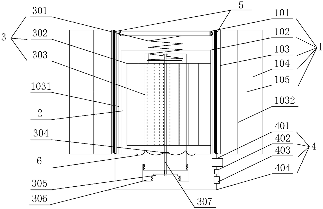
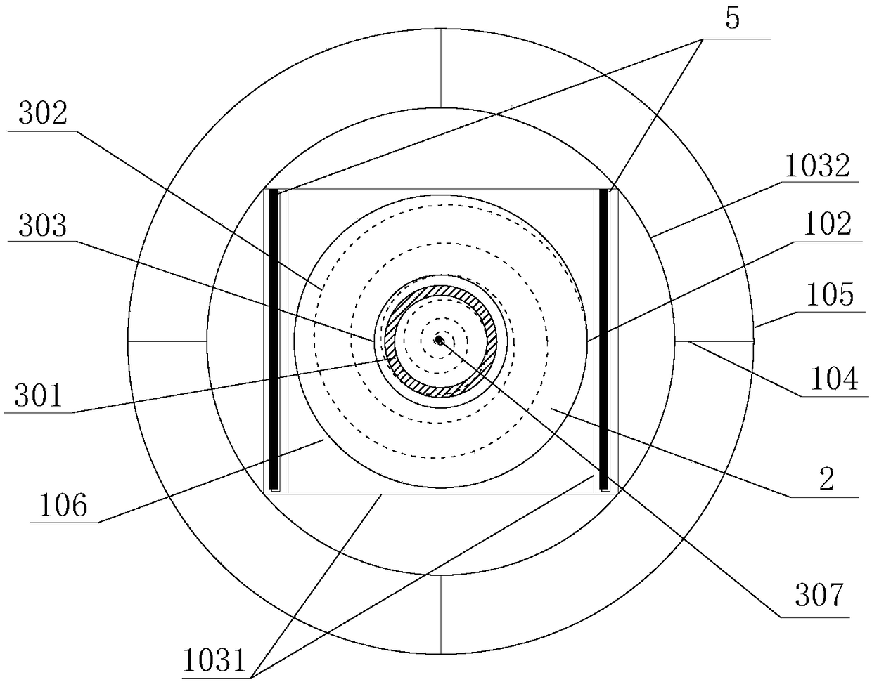
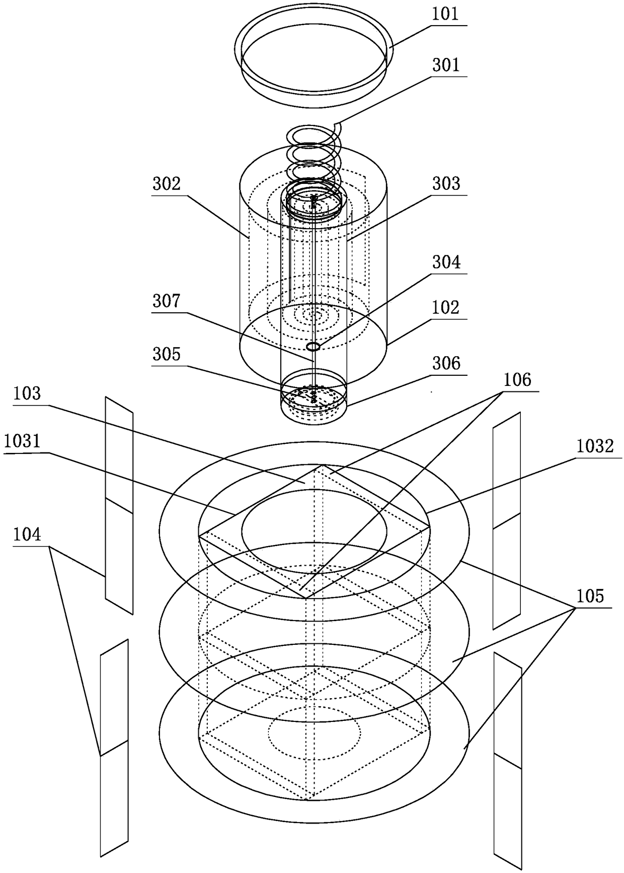
[0022] The detailed description is as follows: A multi-point ground motion test stiffness and damping adjustable boundary system suitable for shaking tables, including force guiding device 1, electrorheological fluid 2, stiffness control device 3, damping control device 4, positive and negative plates 5 and Anti-seepage tarpaulin 6.

[0023] The force guide device 1 is a cylindrical structure as a whole, including a force guide 103, a contact cylinder 102, a horizontal force guide plate 105 and a vertical force guide plate 104; the force guide 103 includes a force guide cover 101 and a cylindrical guide The outer wall 1032 of the force device and the inner wall 1031 of the cube-shaped force guide with the lower opening fixed therein. The horizontal force guide plate 105 and the vertical force gu...


PUM


Abstract

The invention provides a multi-point earthquake motion test rigidity and damping adjustable boundary system suitable for a vibrating table. The multi-point earthquake motion test rigidity and dampingadjustable boundary system suitable for the vibrating table comprises a force guiding device, electrorheological fluid, a rigidity control device, a damping control device, positive and negative plates and seepage-proof tarpaulin. The force guiding device is a cylindrical structure with an opening in the lower portion and comprises a force guider, a contact cylinder, a horizontal force guiding plate and a vertical force guiding plate; the force guider comprises a force guider cover, a force guider outer wall and a force guider inner wall fixed in the opening of the lower surface in the force guider outer wall; the horizontal force guiding plate and the vertical force guiding plate are fixedly connected to the force guider outer wall; the contact cylinder is placed in the force guider innerwall; the rigidity control device has a cylindrical structure, is placed in the contact cylinder and comprises a rigidity controller, a platy annular spring and a disc spring; the seepage-proof tarpaulin is fixedly connected to the lower portion of the force guiding device and the inside of the rigidity controller in a closed manner; and the seepage-proof tarpaulin is in sealed connection with the outer periphery of a seepage-proof bearing, and is in sealed connection with the inner periphery of the force guider inner wall. Rigidities of the spring in multiple directions can be adjusted simultaneously, and the multi-point earthquake motion test rigidity and damping adjustable boundary system suitable for the vibrating table can be applied to simulating an artificial boundary in a multi-point earthquake motion test.

Description

Technical field [0001] The invention relates to the technical field of seismic test devices, and more specifically, to an artificial boundary device of a structural seismic simulation shaking table. Background technique [0002] At present, the seismic shaking tables used for structural seismic tests generally adopt mechanical, electromagnetic and servo-hydraulic types, but these seismic simulation platforms are often aimed at the seismic vibration simulation of small structures. For the seismic response analysis of long-span structures, the traveling wave effect, coherence effect and local site effect during the earthquake propagation process need to be taken into account, so the time and space changes of ground motion must be considered, so the large-span structure is multi-dimensional and multi-point ground motion excitation. However, in the multi-point ground motion test, the existing seismic shaking table is often multi-dimensional and consistent excitation, which cannot be...

Claims


Application Information

Patent Timeline
Patent Type & Authority Applications(China)
IPC IPC(8): F16F13/02F16F9/53
CPCF16F13/02F16F9/532
Inventor 柳国环黄伟纬高云起
Owner TIANJIN UNIV
Why Eureka
Try Eureka