Automatically shifting multi-speed gear transmission

A technology of gear transmission and automatic shifting, applied in the direction of gear transmission, belt/chain/gear, transmission, etc., can solve the problems of easy slippage, high maintenance cost and high requirement of manufacturing process

Pending Publication Date: 2018-08-21
SHAANXI SCI TECH UNIV
View PDF7 Cites 0 Cited by
  • Summary
  • Abstract
  • Description
  • Claims
  • Application Information

AI Technical Summary

Problems solved by technology

However, because the metal chain belt cannot bear large loads and is easy to slip and other defects, its dynamic load is limited and the maintenance cost is high.
Dual-clutch automatic transmission (DCT) uses two sets of clutch mechanisms to shift gears. Although this type of transmission has fast shifting, fuel-saving, and good comfort, the structure of the transmission with this structure is complex and requires high manufacturing processes. It is also high, and the maintenance cost in the later stage is high, especially the heat dissipation strength and bearing capacity of the structure are a pair of contradictions that are difficult to solve
[0004] Comparing several existing commonly used automobile transmissions, it is found that different types of automatic transmissions have defects in transmission efficiency, load capacity, manufacturing process and reliability, etc.

Method used


Image

  • Automatically shifting multi-speed gear transmission
  • Automatically shifting multi-speed gear transmission
  • Automatically shifting multi-speed gear transmission

Examples


Embodiment Construction

[0018] The present invention will be described in detail below in conjunction with the accompanying drawings.

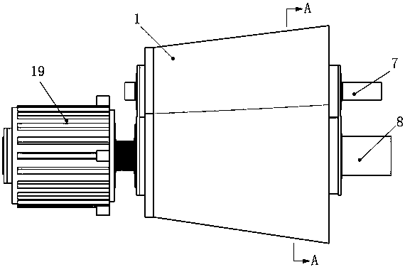
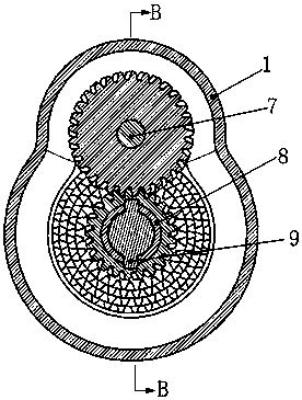
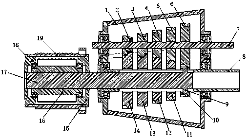
[0019] Such as figure 1 , image 3 , Figure 4 , a multi-stage gear transmission with automatic shifting, including five pairs of cylindrical gear sets, an input shaft 7, an output shaft 8, a direct-acting servo push rod and a housing 1; the housing 1 is fixedly connected to the frame , the input shaft 7 and the output shaft 8 are parallel to each other, and are respectively connected to both ends of the housing 1 through bearings; the direct-acting servo push rod is a servo direct drive device composed of an AC servo motor and a screw nut mechanism, wherein the AC servo The motor rotor 16 of the motor is in the form of a hollow shaft with an internal thread through hole, and the internal thread is exactly the nut in the screw nut mechanism. The two ends of the motor rotor 16 are respectively supported in the motor front end cover 15 and the motor rear end cover 18...


PUM


Abstract

The invention discloses an automatically shifting gear transmission. The automatically shifting gear transmission comprises a main control unit, five pairs of cylindrical gear sets, an input shaft 7,an output shaft 8, a direct acting servo push rod and a casing 1; the direct acting servo push rod is an integrated mechanism composed of an AC (alternating current) servo motor and a leading screw nut mechanism; by controlling the AC servo motor, precise positioning of a cam 9 fixedly connected with a lead screw 17 in the axial position of the output shaft 8 is realized; relying on the cam 9, thefixed connection or the empty sleeve connection between a follower gear provided with a concave hole and emptily sleeving the output shaft 8 and the output shaft 8 is realized; and gear shifting is achieved through the different positions of the cam 9 in the axial of the output shaft 8, and the different participation of a main driving gear and the follower gear in the transmission. The gear shifting process during acceleration and deceleration is completed automatically by a main control unit, and a driver only needs to control the accelerator pedal. The automatically shifting gear transmission is simple and compact in structure, high in transmission efficiency, easy to operate, large in economical value and engineering practical value.

Description

technical field [0001] The invention belongs to the technical field of mechanical automation, and in particular relates to an automatic shifting gear transmission, which is used as a transmission and transmission device in an automobile chassis. Background technique [0002] The transmission is one of the most important parts in the car transmission system. Its main task is to transmit power and change the transmission ratio during the power transmission process to adjust or change the characteristics of the engine. At the same time, it can adapt to different driving requirements through speed change; The performance requirements are getting higher and higher, and the technical improvement of the transmission is undoubtedly an important field of automotive technology innovation; an automatic transmission usually refers to a vehicle transmission that can automatically change the gear ratio during driving, so that the driver does not have to manually shift gears , which simpli...

Claims


Application Information

Patent Timeline
IPC IPC(8): F16H37/12F16H3/083F16H61/02F16H59/36F16H59/44F16H59/68
CPCF16H3/083F16H37/12F16H59/36F16H59/44F16H59/68F16H61/0204F16H61/0248F16H2059/366
Inventor 赵永强张利敏李志峰王长乾
Owner SHAANXI SCI TECH UNIV
Why Eureka
Try Eureka