Brake wheel cylinder stroke detecting device

A stroke detection and braking technology, which is applied to measuring devices, mechanical measuring devices, and mechanical devices, etc., can solve the problems of inability to detect and low accuracy.

Inactive Publication Date: 2018-08-21
ANHUI JIANGHUAI AUTOMOBILE GRP CORP LTD
View PDF16 Cites 0 Cited by
  • Summary
  • Abstract
  • Description
  • Claims
  • Application Information

AI Technical Summary

Problems solved by technology

[0006] Existing drum brake sub-cylinder strokes cannot be detected before or after assembly, or require the cooperation of multiple people to manually use vernier calipers for detection, because the vernier calipers cannot be fixed at a specific position for detection, so the accuracy is low

Method used


Image

  • Brake wheel cylinder stroke detecting device
  • Brake wheel cylinder stroke detecting device
  • Brake wheel cylinder stroke detecting device

Examples


Embodiment Construction

[0030] The embodiments described below by referring to the figures are exemplary only for explaining the present invention and should not be construed as limiting the present invention.

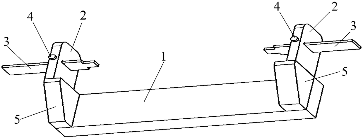
[0031] Embodiments of the present invention: as figure 2 as shown, figure 2 It is an axonometric drawing of the present invention. The present invention proposes a brake cylinder stroke detection device, which includes a base 1, a side plate 2 and a detection caliper 3;

[0032] There are two side plates 2, and the two side plates 2 are arranged in parallel on the same side of the base 1;

[0033] Detection holes are provided on the two side plates 2;

[0034] There are two detection calipers 3, and the two detection calipers 3 slide through the two detection holes respectively.

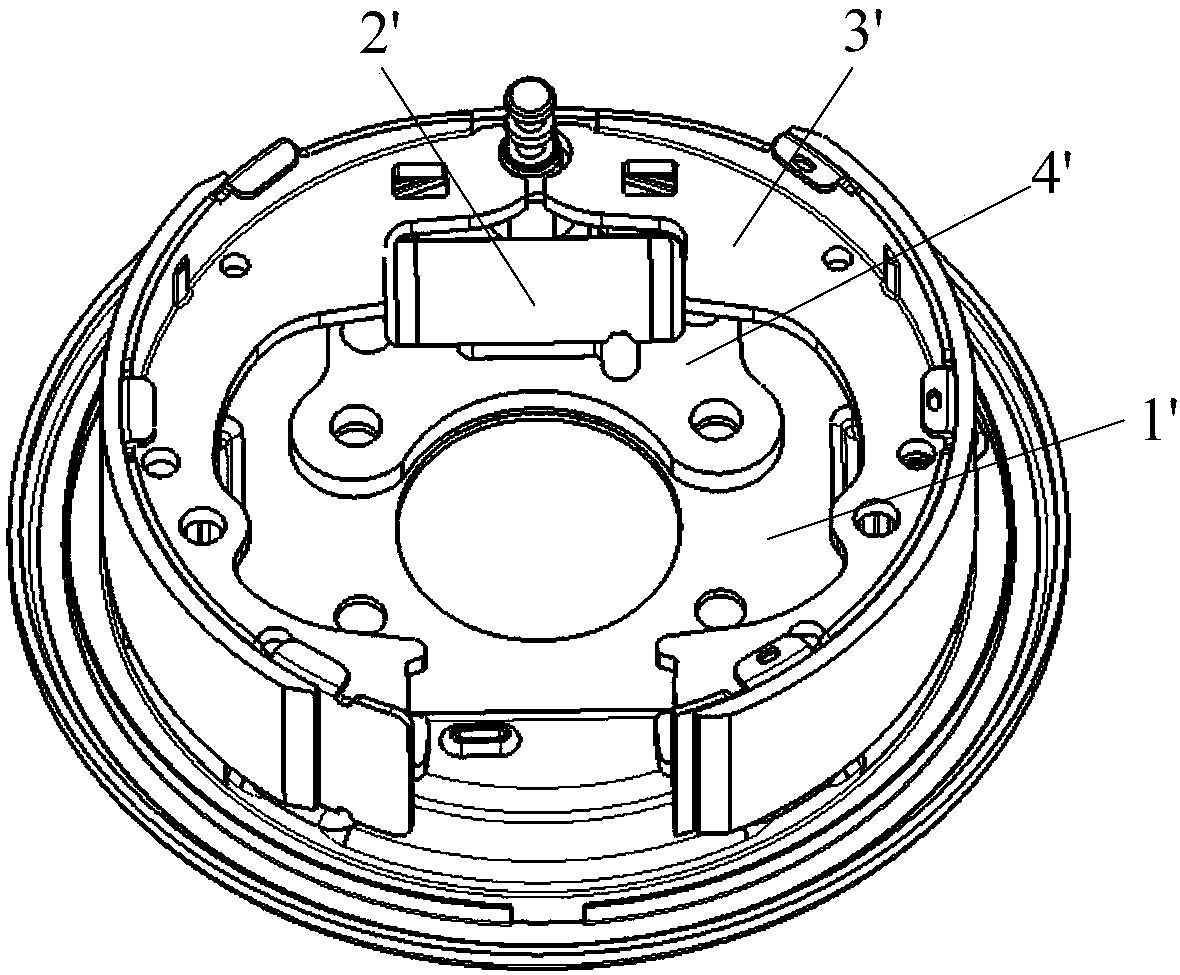
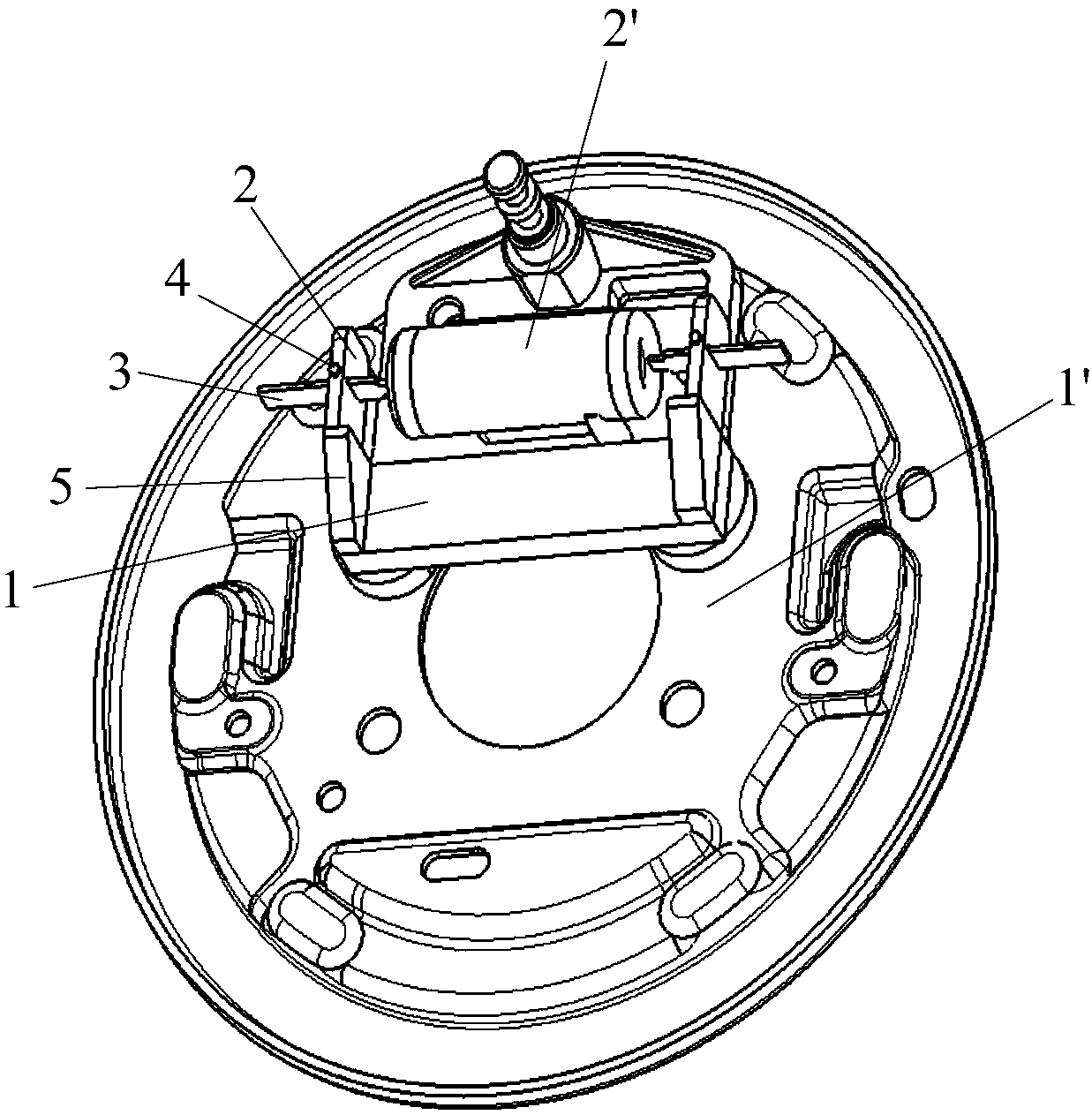
[0035] For specific use, please refer to Figure 3 to Figure 5 , image 3 It is an axonometric drawing of the present invention in use; Figure 4 It is an axonometric view of the present invention under anot...


PUM


Abstract

The invention discloses a brake wheel cylinder stroke detecting device which comprises a base, two side plates and two detecting calipers. The two side plates are arranged on the same side of the basein parallel and each provided with a detecting hole. The two detecting calipers slidingly penetrate through the two detecting holes respectively. The brake wheel cylinder stroke detecting device canconveniently detect the stroke of a drum type brake wheel cylinder.

Description

technical field [0001] The invention relates to the technical field of automobiles, in particular to a brake cylinder stroke detection device. Background technique [0002] The brake is an actuator used to achieve braking. It is usually divided into a driving brake and a parking brake. The parking brake is generally a drum brake at present, which is used for driving and parking braking of the rear wheels. [0003] The drum brake realizes the braking function. Generally, the brake pedal provides the pedal force, and then the brake master cylinder provides the brake oil pressure, which is transmitted to the rear wheel drum brake through the brake pipeline, and the brake pipeline is connected to the drum brake. The sub-cylinder of the brake, the piston inside the sub-cylinder is pushed open under the action of oil pressure, and the brake shoe is stretched, and friction is generated between the brake shoe and the brake drum, which is the braking force. [0004] Please refer to ...

Claims


Application Information

Patent Timeline
IPC IPC(8): G01B5/14G01B5/04
CPCG01B5/14G01B5/046
Inventor 葛飞陈杰张超苏媛高建光郑朋辉叶飞
Owner ANHUI JIANGHUAI AUTOMOBILE GRP CORP LTD
Why Eureka
Try Eureka