Electrical connector

An electrical connector and electrical connection technology, which is applied in the direction of connection, fixed connection, circuit, etc., can solve the problems that the bending part is easy to shake, affects the stable connection between the conductive terminal and the chip module, and lacks the limit function of the bending part. , to achieve the effect of reducing shaking and ensuring stable connection

Active Publication Date: 2018-08-21
DEYI PRECISION ELECTRONIC IND CO LTD PANYU
View PDF5 Cites 2 Cited by
  • Summary
  • Abstract
  • Description
  • Claims
  • Application Information

AI Technical Summary

Problems solved by technology

[0005] However, in this electrical connector, only the barb on the holding part interferes with the corresponding wall surface of the holding groove to hold the conductive terminal in the insulating body. When the chip module presses down on the elastic part, due to the contact part and the holding part The distance between them is relatively large, and the receiving groove lacks a limiting effect on the bending part, which causes the bending part to shake easily in the receiving groove, thereby affecting the stable conduction between the conductive terminal and the chip module

Method used


Image

  • Electrical connector
  • Electrical connector
  • Electrical connector

Examples


Embodiment Construction

[0045] In order to facilitate a better understanding of the purpose, structure, features and effects of the present invention, the present invention will now be further described with reference to the accompanying drawings and specific embodiments.

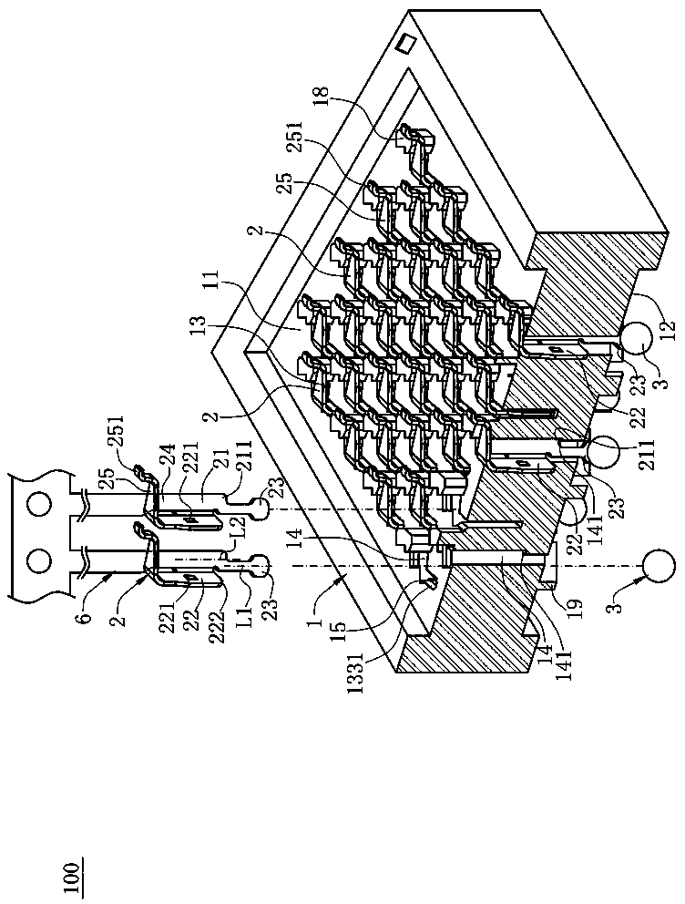
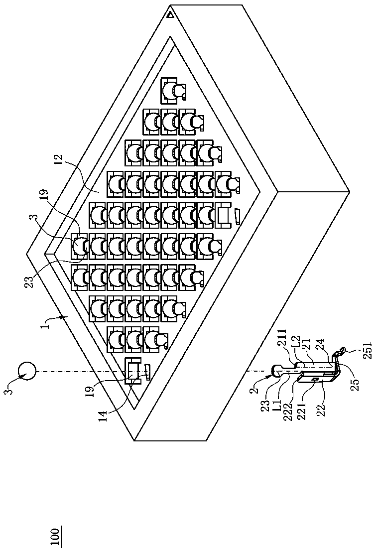
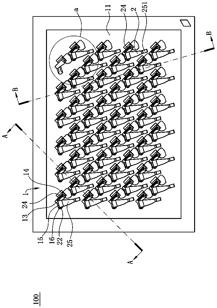
[0046] like Figure 1 to Figure 7 As shown, the electrical connector 100 according to the first embodiment of the present invention is used to electrically connect a chip module 4 to a circuit board 5 , and includes a body 1 for carrying the chip module 4 upward, and a body 1 accommodated in a A plurality of terminals 2 of the body 1 .

[0047] like figure 1 and image 3 As shown, the body 1 is made of insulating material, the body 1 has an upper surface 11 and a lower surface 12 opposite to each other, and the body 1 is provided with a plurality of receiving holes 13 penetrating the upper surface 11 and the lower surface 12 On the surface 12, a plurality of the receiving holes 13 are arranged in multiple rows, and the two adja...


PUM


Abstract

The invention discloses an electrical connector. The electrical connector comprises an insulation body, a first pair of terminals and a second pair of terminals, wherein a slot is formed in the insulation body, the first pair of terminals and the second pair of terminals are arranged on the insulation body and are arranged at the same side of the slot in a staggered way in a longitudinal direction, two first welding parts in the first pair of terminals deviate from two first contact parts in opposite directions in the longitudinal direction, two second welding parts in the second pair of terminals deviate from two second contact parts in opposite directions in the longitudinal direction, and first welding parts of the first pair of terminals and second welding parts of the second pair of terminals are arranged at two opposite sides of a first main body part in a horizontal direction and are arranged at two opposite sides of a second main body part. By arrangement of the paired terminals in a staggered way, the distribution of conductive holes, corresponding to the paired terminals, in a circuit board is facilitated, short-circuit is difficult to cause, moreover, the distribution ofvarious types of terminals is facilitated, so that the connector has relatively good electrical performance during the transmission process.

Description

technical field [0001] The present invention relates to an electrical connector, in particular to an electrical connector that is electrically connected to a chip module. Background technique [0002] The prior art electrical connector related to the present invention is used for electrically connecting a chip module to a circuit board, and includes an insulating body and a plurality of conductive terminals accommodated in the insulating body. [0003] The conductive terminal is made of metal material by integral stamping, which includes a flat plate-shaped holding part, a bending part bent and extended from one side of the holding part, an elastic part bent upwardly and extended from the top of the bending part, and The bottom end of the holding part is bent downward and extends to the welding part. Wherein, there are several barbs on opposite sides of the holding part. The end of the elastic portion is provided with an arc-shaped contact portion, which can be conductivel...

Claims


Application Information

Patent Timeline
Patent Type & Authority Applications(China)
IPC IPC(8): H01R13/02H01R13/24H01R13/40
CPCH01R13/02H01R13/24H01R13/40H01R12/57H01R12/7076H01R12/714H01R13/2464H01R13/41H01R12/52H01R12/55H01R13/502H01R13/514
Inventor 朱德祥周志勇金左锋
Owner DEYI PRECISION ELECTRONIC IND CO LTD PANYU
Why Eureka
Try Eureka