Medical clip and treatment tool system
A disposal device and medical technology, which is applied in the field of medical fixtures and disposal device systems, can solve the problem that the top of the disposal device is far away from the target site, and achieve the effect of simple installation and disassembly, and reliable retention
- Summary
- Abstract
- Description
- Claims
- Application Information
AI Technical Summary
Problems solved by technology
Method used
Image

Examples
no. 1 approach
[0058] Below, refer to Figure 1 to Figure 24 The first embodiment of the present invention will be described.
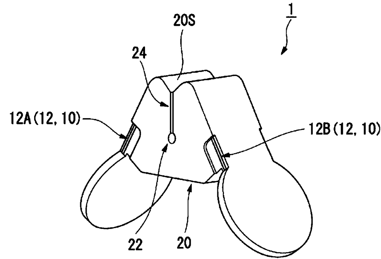
[0059] figure 1 It is a perspective view showing the medical clip 1 of the first embodiment. The medical clip 1 includes a frame 10 and an elastic member 20 .
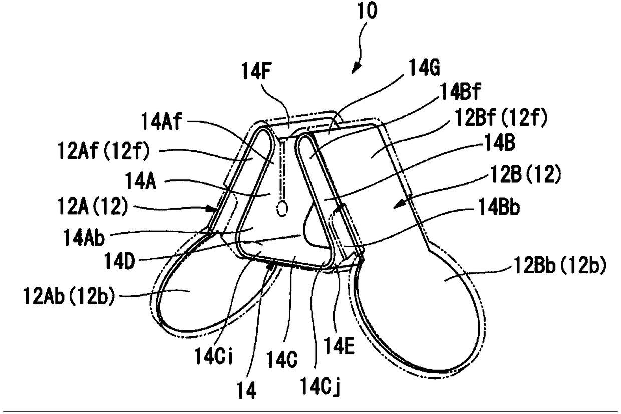
[0060] figure 2 It is a figure which shows the frame 10 of the medical clip 1. exist figure 2 In , the dashed-two dotted line indicates the shape of the medical jig 1 . The frame 10 includes a pair of gripping portions 12 composed of a first gripping portion 12A and a second gripping portion 12B, and a pair of gripping portions 12 connected, that is, connecting the first gripping portion 12A and the second gripping portion 12B. Connecting part 14. In addition, in this embodiment, the frame 10 is formed by bending a rigid plate-shaped member.
[0061] The pair of gripping parts 12 are formed so as to extend from the front end part 12f to the rear end part 12b, and are provided to be separated from ...
example 1
[0094] exist Figure 12 In step S1 shown, the medical jig 1 is attached to the ultrasonic probe 50 and the forceps 60 used as the treatment tool 40 in this technique. First, the amount of protrusion of the ultrasonic probe 50 from the tip of the guide sheath 30 is set in advance. The medical clip 1 is attached to the insertion portion 51 at a position corresponding to the protrusion amount. Next, the amount of protrusion of the forceps 60 from the tip of the guide sheath 30 is set. The amount of protrusion of the pliers 60 is set to be the amount of protrusion from the tip of the guide sheath 30 at the position of the ultrasonic vibrator 57 of the ultrasonic probe 50 and the amount of protrusion from the tip of the guide sheath 30 at the position of the gripping portion 68 of the pliers 60 . The amount of protrusion is equal. Another medical clip 1 is attached to the insertion portion 61 at a position corresponding to the protrusion amount.
[0095] Figure 13 It is a dia...
no. 2 approach
[0130] Next, refer to Figure 25 ~ Figure 27 A second embodiment of the present invention will be described.
[0131] Figure 25 It is a perspective view showing the medical clip 3 of this embodiment. The medical clip 3 is different from the medical clip 1 of the first embodiment in that it further includes a restricting member 96 provided between the pair of gripping parts 12 . In addition, the detailed description of the part which has the same structure as the medical clip 1 of 1st Embodiment is abbreviate|omitted.
[0132] Figure 26 It is a front view showing the medical jig 3 . Figure 27 is the medical fixture 3 with Figure 5 It is a sectional view of a section corresponding to the section of the medical clip 1 shown. The restricting member 96 is provided between the pair of gripping parts 12 for restricting the movement range in which the front end parts 12 f of the pair of gripping parts 12 approach and separate. In the present embodiment, the restricting memb...
PUM
 Abstract
Description
Claims
Application Information
 - R&D Engineer
- R&D Manager
- IP Professional
- Industry Leading Data Capabilities
- Powerful AI technology
- Patent DNA Extraction
Browse by: Latest US Patents, China's latest patents, Technical Efficacy Thesaurus, Application Domain, Technology Topic.
© 2024 PatSnap. All rights reserved.Legal|Privacy policy|Modern Slavery Act Transparency Statement|Sitemap