Shaft sleeve feeding system

A technology of feeding system and bushing, applied in the direction of grinding feed motion, grinding machine parts, metal processing equipment, etc., can solve the problems of increased labor and low efficiency, and achieve high work efficiency, continuous feeding, automation high degree of effect

Inactive Publication Date: 2018-08-24
林淑录
View PDF6 Cites 2 Cited by
  • Summary
  • Abstract
  • Description
  • Claims
  • Application Information

AI Technical Summary

Problems solved by technology

[0002] The shaft sleeve is an important mechanical part, which is widely used on the gear shaft or bearing to fix the center position of the shaft and the bearing to prevent it from shifting due to vibration during operation; when the existing shaft sleeve workpiece is processed , which generally place the bushing on the box, transport the bushing workpiece to be processed to the grinding machine through tools such as a cart, and then manually load the material for processing, which needs to be manually taken from the box, and generally Because the countertop is relatively small, the box is generally placed on the ground, so that people take materials up and down, which increases the workload, and is very tiring, and its efficiency is also low

Method used


Image

  • Shaft sleeve feeding system
  • Shaft sleeve feeding system
  • Shaft sleeve feeding system

Examples


Embodiment Construction

[0031] The embodiments of the present invention will be described in detail below with reference to the accompanying drawings, but the present invention can be implemented in many different ways defined and covered by the claims.

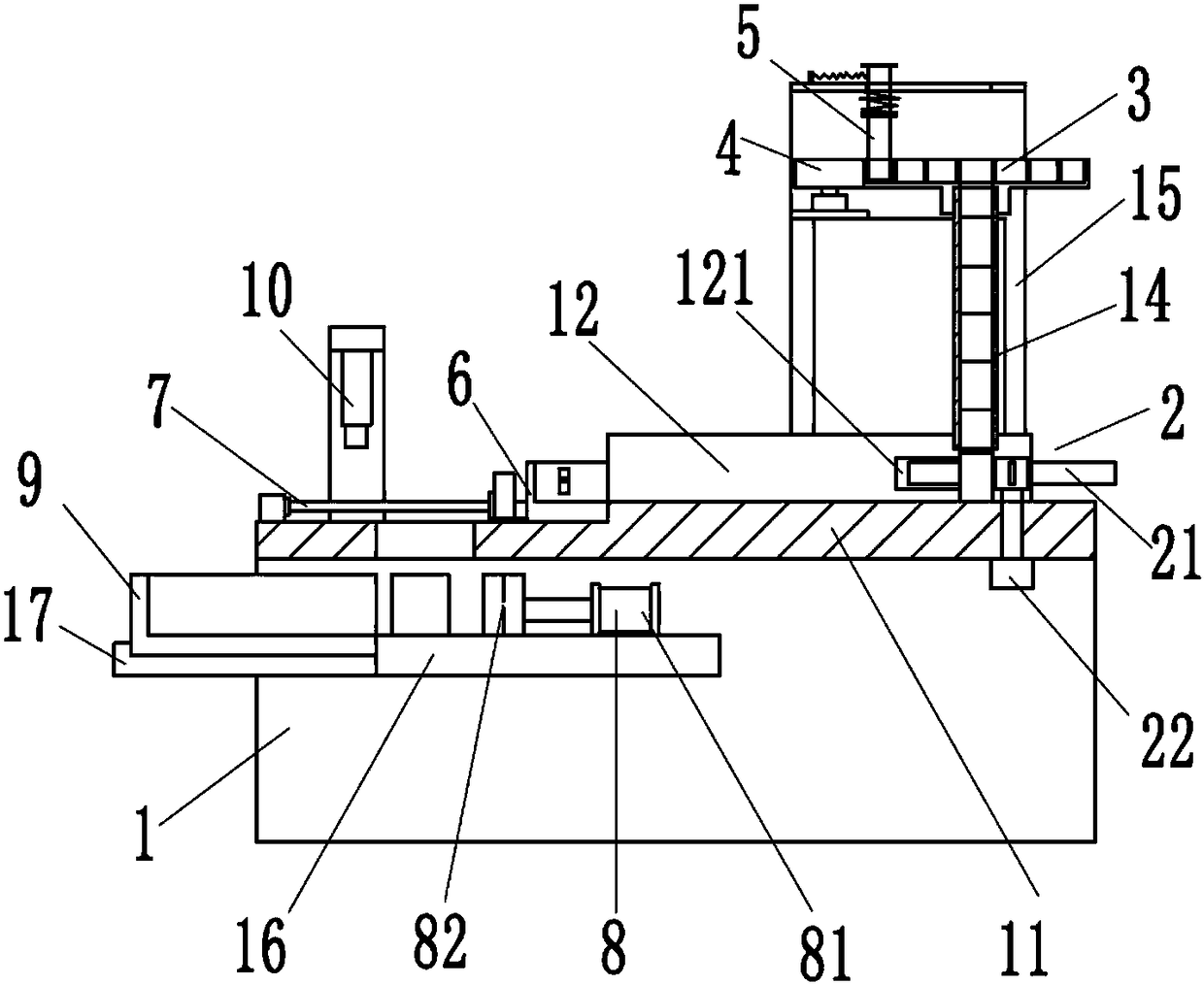
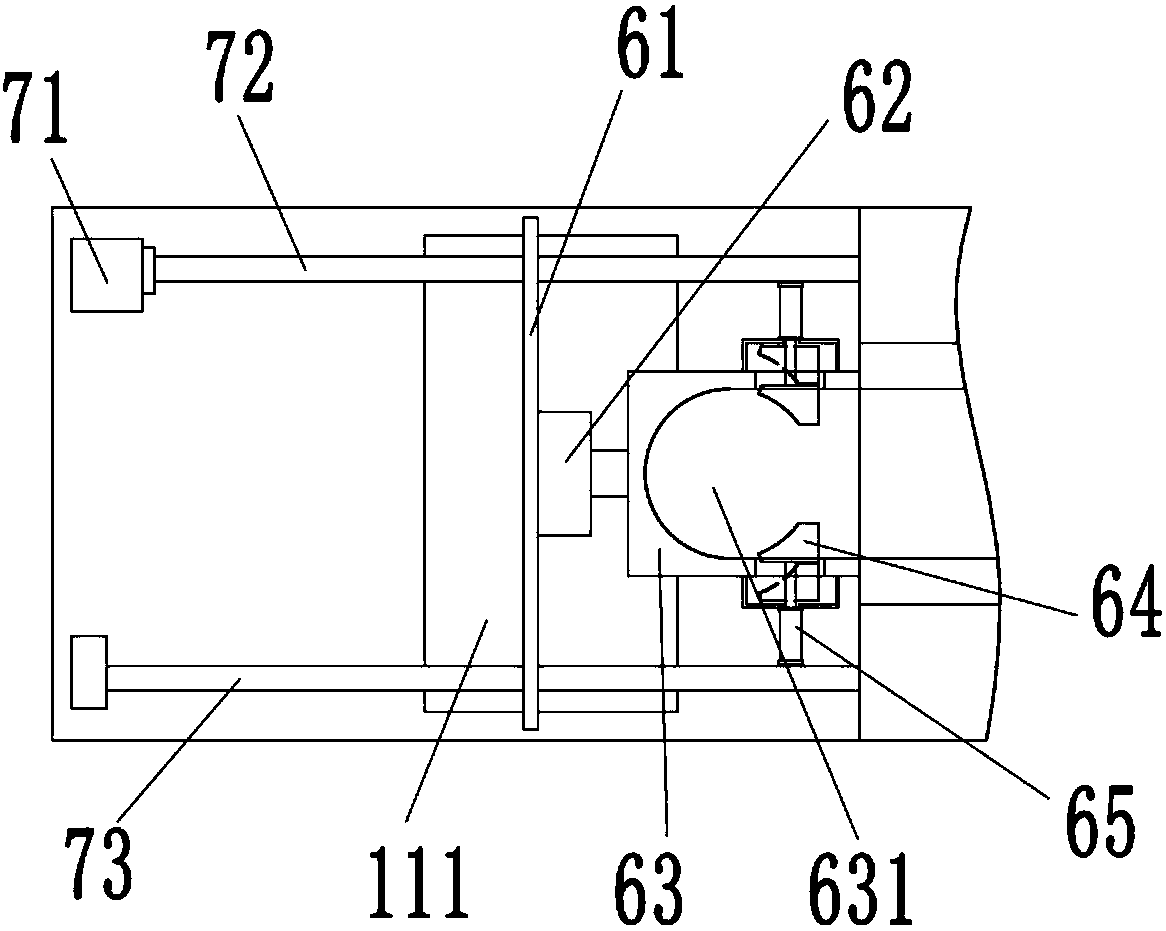
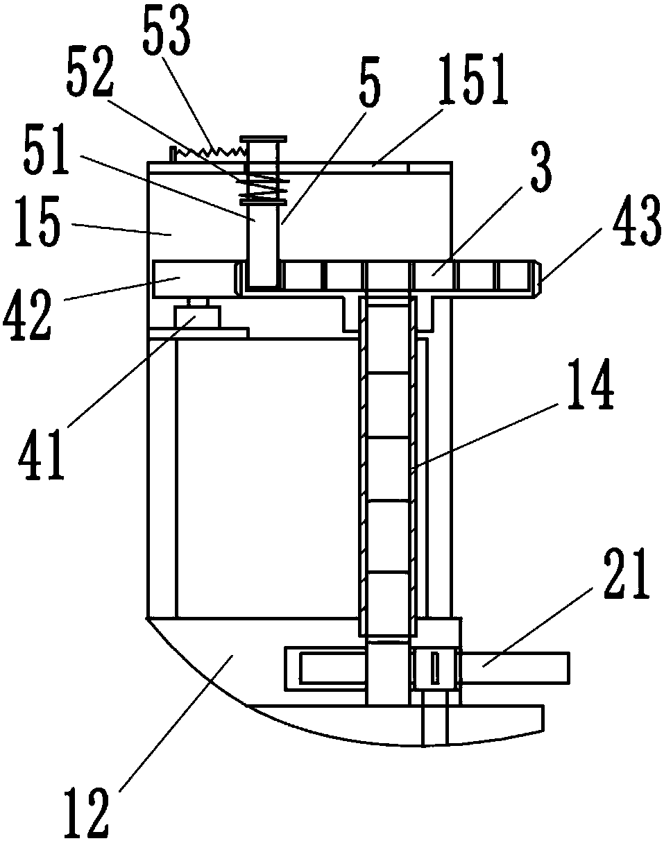
[0032] Refer below Figure 1 to Figure 5 To further explain this application, such as figure 1 and figure 2 A shaft sleeve feeding system shown includes: a door-shaped base 1, a material shifting device 2, a material tray 3, a material tray driving device 4, a material pushing device 5, a moving clamping seat 6, a moving driving mechanism 7, and a feeding mechanism 8 and the receiving tray 9, a pair of side plates 12 are arranged on the right end of the table 11 of the door-shaped base 1, a slideway 13 is formed between the pair of side plates 12, and a slideway 13 is fixed above the slideway 13. Material pipe 14, the table top 11 is provided with a door-shaped bracket 15, the feeding pipe 14 is located in the door-shaped bracket 15, the left end...


PUM


Abstract

The invention provides a shaft sleeve feeding system. The shaft sleeve feeding system comprises a portal base, a material shifting device, a material plate, a material plate driving device for drivingthe material plate to rotate, a material pushing device, a movable clamping base and a movement driving mechanism for driving the movable clamping base to move. A pair of side plates is arranged on the top board of the portal base. A slideway is formed between the pair of side plates. A discharging pipe is arranged on the upper portion of the slideway. A window penetrating through the upper end face and the lower end face of the top board is arranged on the top board. A material shifting wheel of the material shifting device is pivoted to the top board and can push shaft sleeves to slide along the slideway when rotating. The material plate is movably arranged at the top end of the discharging pipe in a sleeving mode. The shaft sleeves are enabled by the material pushing device to enter the discharging pipe through a center hole of the material plate. The movable clamping base is used for clamping and fixing the shaft sleeves sliding out of the slideway. The processed shaft sleeves canpass through the window to fall to a material receiving plate under the action of an overturning air cylinder. According to the shaft sleeve feeding system provided by the invention, continuous feeding can be achieved, the automation degree is high, and application is convenient.

Description

technical field [0001] The invention relates to a feeding system, in particular to a shaft sleeve feeding system. Background technique [0002] The shaft sleeve is an important mechanical part, which is widely used on the gear shaft or bearing to fix the center position of the shaft and the bearing to prevent it from shifting due to vibration during operation; when the existing shaft sleeve workpiece is processed , which generally place the bushing on the box, transport the bushing workpiece to be processed to the grinding machine through tools such as a cart, and then manually load the material for processing, which needs to be manually taken from the box, and generally Because the table is relatively small, the box is generally placed on the ground, so that people take materials up and down, which increases the workload, and is very tiring, and its efficiency is also low. Contents of the invention [0003] The purpose of the present invention is to overcome the deficien...

Claims


Application Information

Patent Timeline
Patent Type & Authority Applications(China)
IPC IPC(8): B24B41/00
CPCB24B41/005
Inventor 林淑录
Owner 林淑录
Why Eureka
Try Eureka