Microsatellite structure suitable for optical load

A micro-satellite and payload technology, which is applied to artificial satellites, space navigation equipment, space navigation vehicles, etc., can solve the problems of increasing structural quality and design complexity, reducing weight and hollowing out design, increasing design difficulty, etc., and achieving good results. Market application prospects, good operation, and the effect of shortening the force transmission path

Inactive Publication Date: 2018-08-24
AEROSPACE DONGFANGHONG SATELLITE
View PDF5 Cites 9 Cited by
  • Summary
  • Abstract
  • Description
  • Claims
  • Application Information

AI Technical Summary

Problems solved by technology

However, this structure also has the problems of less equipment installation surface and higher material density.
In addition, when there are a large number of devices on the mounting surface of a certain structure, it is necessary to consid

Method used


Image

  • Microsatellite structure suitable for optical load
  • Microsatellite structure suitable for optical load
  • Microsatellite structure suitable for optical load

Examples


Example Embodiment

[0025] In order to make the solution of the present invention clearer, the present invention will be further described below in conjunction with the accompanying drawings and specific embodiments:

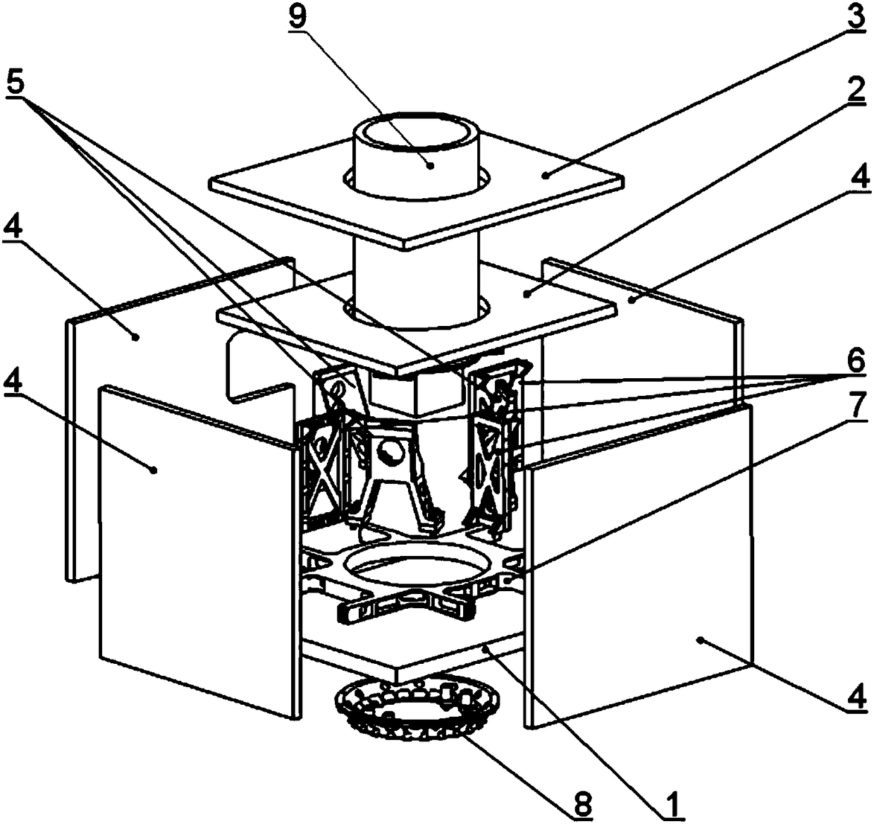
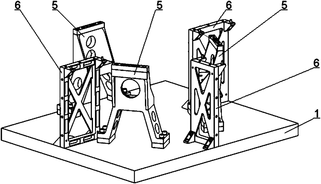
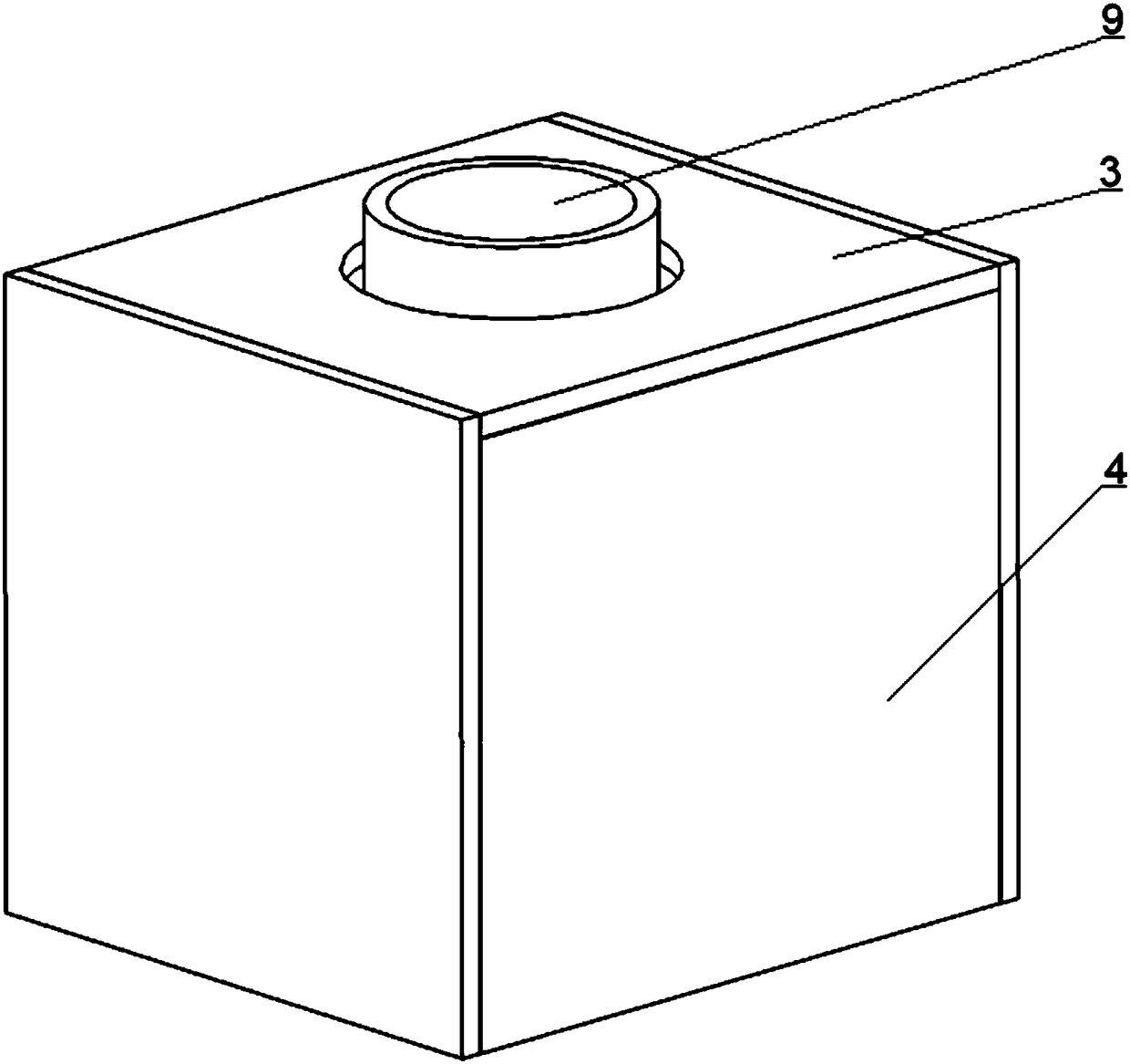
[0026] like Figure 1~3 As shown, a micro-satellite structure suitable for optical loads, including a bottom plate 1, a middle plate 2, a top plate 3, a side plate 4, a bracket 5, a bulkhead 6, a bottom plate strengthening embedded part 7, a docking ring 8 and a load 9; the bottom plate 1. The middle plate 2, the top plate 3 and the side plate 4 all adopt a rectangular plate structure. The bottom plate reinforcement embedded parts 7 for reinforcing the structure are embedded in the bottom plate 1, and the bracket 5 for supporting the load 9 is installed on the upper surface of the bottom plate 1. The bottom surface of the bottom plate 1 is equipped with a docking ring 8; the middle plate 2 and the top plate 3 are provided with through holes for passing through the load 9; Connecte...


PUM


Abstract

The invention discloses a microsatellite structure suitable for an optical load. The structure comprises a bottom board, an intermediate board, a top board, side boards, supports, separation frames, abottom board reinforcing embedded part, a docking ring and the load. The bottom board, the intermediate board, the top board and the side boards are each of a rectangular board structure. The bottomboard reinforcing embedded part used for reinforcing the structure is pre-buried in the bottom board. The supports used for supporting the load are installed on the upper surface of the bottom board.The docking ring is installed on the lower surface of the bottom board. Through holes allowing the load to penetrate through are formed in the intermediate board and the top board. The bottom board, the intermediate board and the top board are parallel, and the edges of the bottom board, the intermediate board and the top board are perpendicularly and fixedly connected with the four side boards toform a box-type structure. The multiple separation frames used for reinforcing the rigidity are installed between the bottom board and the intermediate board. Through cooperation of the bottom board,the intermediate board, the top board, the side boards, the supports, the separation frames, the bottom board reinforcing embedded part, the docking ring and the load, the force transferring path ofthe optical load is shortened, the structural layout of a whole microsatellite is optimized, and the defects that parts of a traditional microsatellite truss structure are concentrated, and the mass is large are overcome.

Description

technical field [0001] The invention relates to a micro-satellite structure suitable for optical loads, in particular suitable for micro-satellites with an optical load of 50-100 kg, and belongs to the technical field of micro-satellite load assembly structures. Background technique [0002] Compared with traditional satellites, the microsatellite structure has the characteristics of small space, more equipment, high density, and high integration. Due to the space requirements of optical load microsatellites, the density of equipment in the satellite is higher. At the same time, the ratio of optical load to the weight of the whole star is relatively large, and the load is relatively concentrated. [0003] At present, microsatellites (such as CubeSat, etc.) generally adopt a metal truss structure, using metal plates to provide equipment mounting surfaces, and hollowing out appropriate parts to reduce weight to form a single truss, and several truss structures are combined to ...

Claims


Application Information

Patent Timeline
IPC IPC(8): B64G1/10
CPCB64G1/10B64G1/223
Inventor 韩建斌刘江岳冠楠段晓高振邦
Owner AEROSPACE DONGFANGHONG SATELLITE
Why Eureka
Try Eureka