Pressing device for planar antenna and layout method

A technology of a pressing device and a plane antenna, which is applied in the field of aerospace vehicles, can solve the problems of difficulty in ensuring accuracy, increased thickness of the antenna, and increased release stroke of the pressing rod, so as to solve the interference problem, improve the reliability, and reduce the processing difficulty. Effect

Pending Publication Date: 2022-01-04
SHANGHAI AEROSPACE SYST ENG INST
View PDF0 Cites 0 Cited by
  • Summary
  • Abstract
  • Description
  • Claims
  • Application Information

AI Technical Summary

Problems solved by technology

[0003] a. In the traditional locking scheme, when multiple panels are unfolded, movement interference between the compression rod and the antenna panel is very likely to occur, and there is a hidden danger of hooking, which in turn affects the reliability of unlocking;
[0004] b. For devices that use elastic elements to realize unlocking, due to the increase in antenna thickness caused by multi-layer boards, the release stroke of the pressing rod will increase significantly, making the outer envelope of the pressing mechanism easily exceed the safety boundary of the carrying fairing ;
[0005] c. The pin positioning method is used, which makes it difficult to process the star mounting surface and the accuracy is difficult to guarantee

Method used


Image

  • Pressing device for planar antenna and layout method
  • Pressing device for planar antenna and layout method
  • Pressing device for planar antenna and layout method

Examples


Embodiment 1

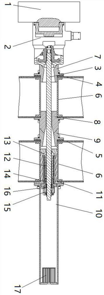
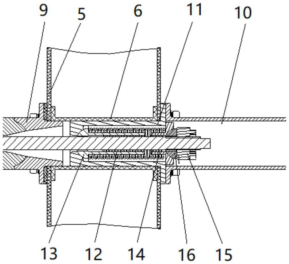
[0045] see figure 1 and figure 2 , the present embodiment provides a pressing device 01 facing a planar antenna, which is used for pressing two adjacent antenna boards. Among the two adjacent antenna boards, the one close to the satellite platform 1 is the first antenna board 4, and the other is the first antenna board 4. The second antenna board 5 , the first antenna board 4 and the second antenna board 5 are all provided with through holes for passing the pressing device 01 .

[0046] The pressing device 01 includes a first connecting piece, a second connecting piece, a third connecting piece, a force applying sleeve 11, a spring 12, a fastener, a pressing rod 3, an outer sleeve 10 and a lock fixed to the satellite platform 1 Tight parts. According to the distance from the satellite platform 1 from near to far, it is the locking part, the first connecting part, the first antenna board 4, the second connecting part, the third connecting part, the second antenna board 5 and...

Embodiment 2

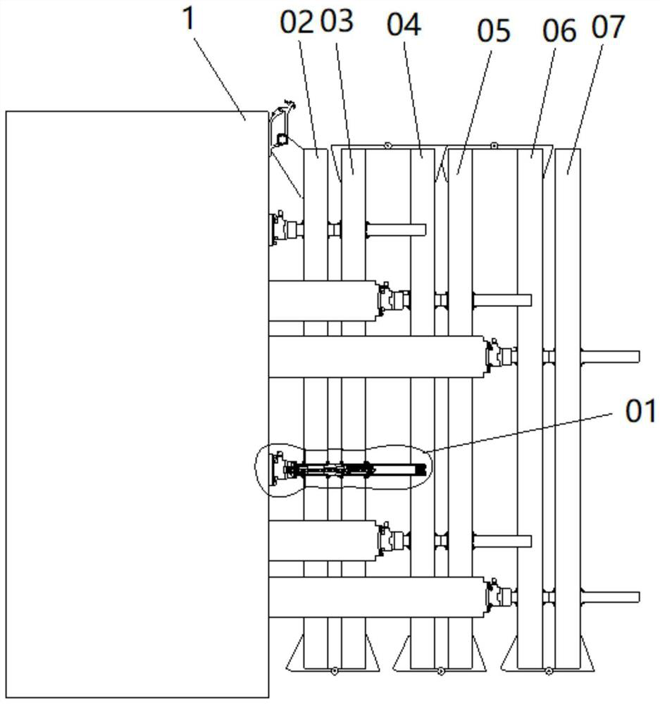
[0061] see image 3 , this embodiment provides a planar antenna-oriented pressing device layout method based on Embodiment 1.

[0062] According to distance from the satellite platform 1, every two antenna boards are divided into one group of antenna board groups from near to far, and the two antenna boards in each group of antenna board groups adopt the pressing device 01 facing the planar antenna as in Embodiment 1. Compression, all the compression devices 01 cooperate with each other to compress all the antenna boards to the folded state.

[0063] Taking six antenna boards as an example, they are antenna board A 02, antenna board B 03, antenna board C 04, antenna board D 05, antenna board E 06 and antenna board F 07 according to the distance from satellite platform 1 from near to far. The six antenna boards are divided into three layers, antenna board A02 and antenna board B 03 are a group of antenna boards, antenna board C 04 and antenna board D 05 are a group of antenna ...


PUM


Abstract

The invention discloses a pressing device for a planar antenna and a layout method. The pressing device comprises a first sleeve, a pressing rod, an embedded part, a second sleeve, a third sleeve, a force application sleeve, an outer sleeve, a honeycomb pad, a pressing nut, a spherical pad, a spring top sleeve, a compression spring, a spring bottom sleeve and a separation nut. The pressing device takes two antenna plates as a group and is respectively connected with a satellite platform, so that 'layered pressing' between a plurality of plates and a satellite body is realized. According to the invention, the release stroke of the pressing device is not influenced by the number of the antenna plates, and the connection of a plurality of plates and a star body is converted into a connection structure form of two plates and the star body, so that the reliability of unlocking is improved; the shell and the star platform are positioned and reset through the separation nut, and compared with a pin positioning mode, the problems that the machining difficulty of a star mounting surface is large, and the precision is difficult to guarantee are solved; and compression among a plurality of antenna plates is transmitted through the embedded parts, and compared with a traditional sleeve for transmitting force, the compression effect of the antenna is better.

Description

technical field [0001] The invention belongs to the technical field of aerospace vehicles, and in particular relates to a pressing device and a layout method for planar antennas. Background technique [0002] At home and abroad, there are many researches and applications on the pressing mechanism of satellite solar cell wings. Compared with the solar wing, the SAR planar antenna has the characteristics of heavy load and thick size. At present, the compression of SAR planar antennas is divided into two types according to the structural form, mainly perforated and non-perforated. Non-perforated type such as compression lock, because it can only be between the star and the antenna, so it is only suitable for locking a single antenna plate; while the perforated type can be used for locking two antenna plates, such as foreign applications are more typical There is Canada's RADARSAT satellite, which uses a compression rod to connect two antenna panels. However, for the structura...

Claims


Application Information

Patent Timeline
IPC IPC(8): H01Q1/12
CPCH01Q1/12H01Q1/1207Y02D30/70
Inventor 李波曾文花陈鸿汤炜陈永香
Owner SHANGHAI AEROSPACE SYST ENG INST
Why Eureka
Try Eureka