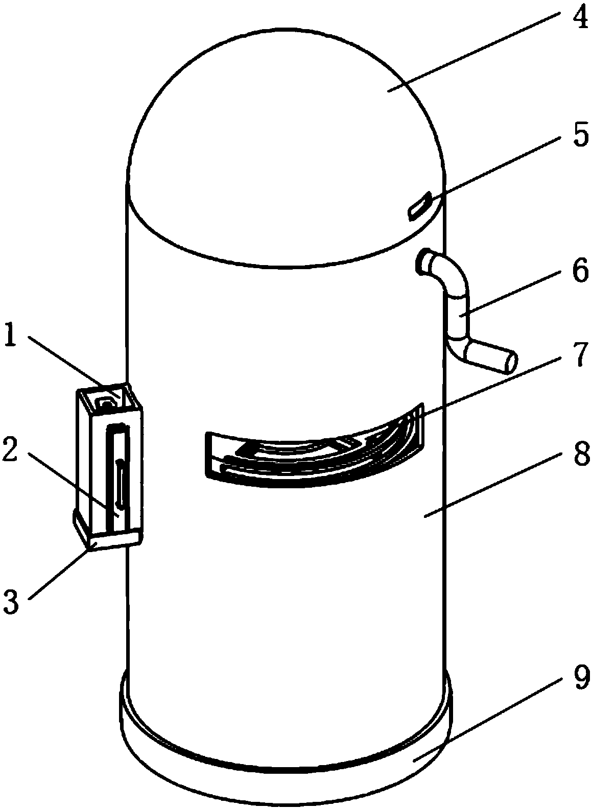
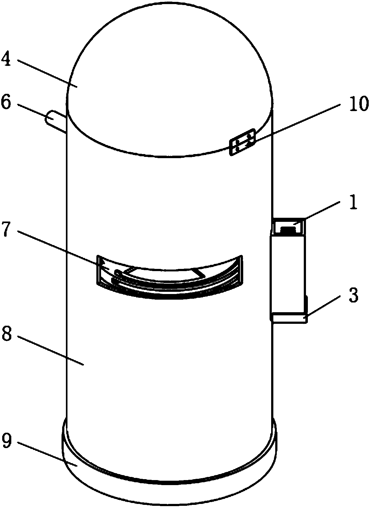
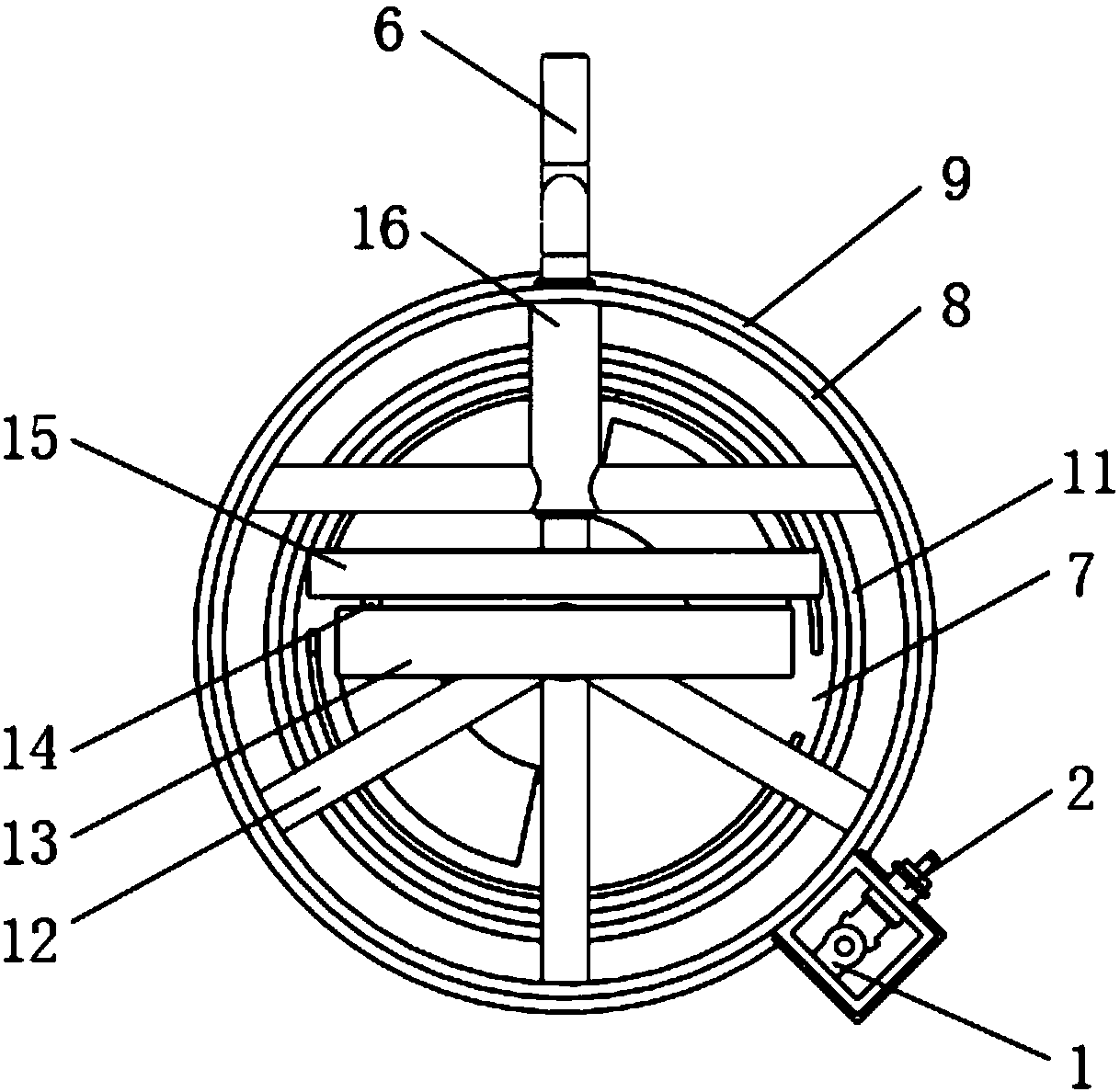
Ward garbage can with compression function

A technology for trash cans and wards, which is applied in the field of trash cans and trash cans for wards, which can solve the problems of troublesome garbage cleaning, lack of compressed garbage, single function, etc., and achieve the effect of increasing the stability of the ground

Inactive Publication Date: 2018-08-24
李如意
View PDF5 Cites 2 Cited by
  • Summary
  • Abstract
  • Description
  • Claims
  • Application Information

AI Technical Summary

Problems solved by technology

Hospital wards are special rooms. In addition to meeting the basic needs of collecting garbage, the garbage cans used in hospital wards should also have the function of being easy to move and compress garbage. At present, most of the commonly used garbage cans are barrel-shaped structures with a closed bottom and an open top. , the structure is simple, the function is single, and it does not have the function of compressing garbage. When it is used, it directly throws the garbage into the trash can without any treatment of the garbage. Because the gap between the garbage is large, it is easy to fill the trash can. There are many people in the upper ward, which

Method used


Image

  • Ward garbage can with compression function
  • Ward garbage can with compression function
  • Ward garbage can with compression function

Examples


Embodiment Construction

[0047] The following will clearly and completely describe the technical solutions in the embodiments of the present invention with reference to the accompanying drawings in the embodiments of the present invention. Obviously, the described embodiments are only some, not all, embodiments of the present invention. Based on the embodiments of the present invention, all other embodiments obtained by persons of ordinary skill in the art without making creative efforts belong to the protection scope of the present invention.

[0048] The terms "first", "second", and the like in the description and claims of the present invention and the above drawings are used to distinguish similar objects, and are not necessarily used to describe a specific sequence or sequence. It is to be understood that the data so used are interchangeable under appropriate circumstances such that the embodiments of the invention described herein are, for example, capable of practice in sequences other than thos...


PUM


Abstract

The invention relates to a garbage can, in particular to the ward garbage can with a compression function, and belongs to the technical field of environmental protection devices. The ward garbage cancomprises a fixing seat, a pressing head, a tray, a bending shaft, a lower pressing plate, an outer can, a supporting seat, an inner can, a first supporting frame, a horizontal sliding way, a connecting shaft, a rotating disc, a second supporting frame, a pressing rod, a square sliding block and the like; and the pressing head is inserted into the fixing seat, the tray is buckled at the lower endof the fixing seat, the lower end of the outer can is inserted into the supporting seat, the bending shaft penetrates through the outer can and the second supporting frame to be fixedly connected withthe rotating disc, one end of the connecting shaft is fixedly connected with the rotating disc, the other end of the connecting shaft is connected with the square sliding block in a rotatable mode, the upper end of the pressing rod is fixedly connected with the horizontal sliding way, the lower end of the pressing rod penetrates through the first supporting frame to be fixedly connected with theupper end surface of the lower pressing plate, and the lower end of the inner can is inserted into the supporting seat and is in interference fit with the supporting seat. The ward garbage can has thebeneficial effects that the basic requirements of collecting garbage can be met, and moreover, the ward garbage can also has the functions of being convenient to move and capable of compressing the garbage and bending toothpicks.

Description

technical field [0001] The invention relates to a garbage can, in particular to a garbage can used in a ward with a compression function, and belongs to the technical field of environmental protection equipment. Background technique [0002] Trash can, also known as waste bin or dustbin, is a container for storing rubbish. Hospital wards are special rooms. In addition to meeting the basic needs of collecting garbage, the garbage cans used in hospital wards should also have the function of being easy to move and compress garbage. At present, most of the commonly used garbage cans are barrel-shaped structures with a closed bottom and an open top. , the structure is simple, the function is single, and it does not have the function of compressing garbage. When it is used, it directly throws the garbage into the trash can without any treatment of the garbage. Because the gap between the garbage is large, it is easy to fill the trash can. There are many people in the upper ward, ...

Claims


Application Information

Patent Timeline
IPC IPC(8): B65F1/14B65F1/06B65F1/08
CPCB65F1/1405B65F1/06B65F1/08B65F1/14B65F1/1473B65F2210/162B65F2210/169
Inventor 李如意
Owner 李如意
Why Eureka
Try Eureka