
Pressing plate mechanism of in-out pallet

A technology of pressing plates and pallets, which is applied in the direction of conveyor objects, furnaces, charge manipulation, etc., and can solve the problems of affecting the quality of electronic component placement, deformation of thin PCB circuit boards, and easy deformation.

Active Publication Date: 2018-08-24
浙江华企正邦自动化科技有限公司
View PDF11 Cites 0 Cited by
  • Summary
  • Abstract
  • Description
  • Claims
  • Application Information

AI Technical Summary

Problems solved by technology

[0004] As we all know, there are many types of PCB circuit boards. When performing the third step above, some thin PCB circuit boards will be deformed during the clamping process, or the original PCB circuit boards have deformation phenomena. For example, PCB circuit boards with a thickness of 1mm and below are most likely to be deformed during this process, resulting in the inability of solder paste or glue to be completely screen-printed on the surface of the PCB circuit board, thereby affecting subsequent electronic components. Packing quality
[0005]When the traditional SMT printing machine is printing on the above-mentioned PCB circuit board, a pressing piece is added on the guide rail of the in-out board, and some solder paste or glue appears after the installation Thickness, which wastes solder paste or glue, and may affect the quality of subsequent processing

Method used


Image

  • Pressing plate mechanism of in-out pallet
  • Pressing plate mechanism of in-out pallet
  • Pressing plate mechanism of in-out pallet

Examples


Embodiment Construction

[0044] The present invention will be further described below in conjunction with the accompanying drawings.

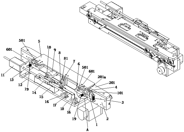
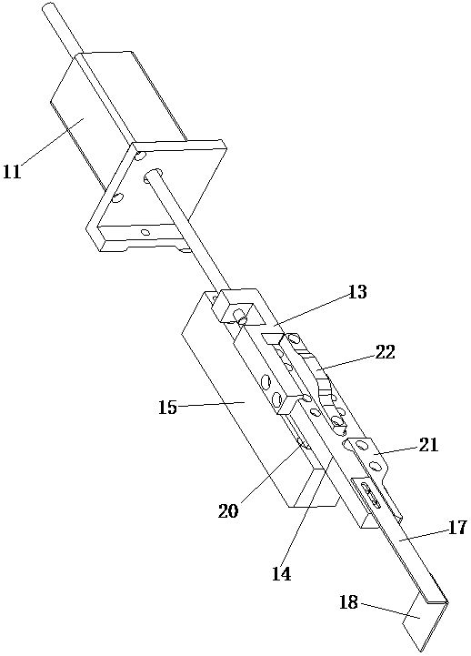
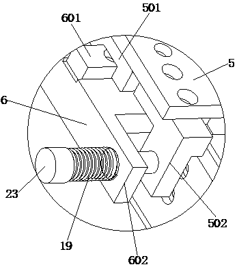
[0045] Such as Figures 1 to 3 As shown, a pressing plate mechanism for entering and exiting a pallet according to the present invention includes two pressing plate assemblies, and the pressing plate assemblies are used in pairs, and this example is preferably used symmetrically. The pressing plate assembly includes a lifting plate 1 , an in-out plate track 2 and a PCB pressing plate 5 . The PCB circuit board is not shown in the figure and is sent to the directly below the printing screen layout through the conveyor belts on the two entry and exit board tracks 2 .

[0046]The PCB pressing plate 5 is connected with the lifting plate 1 through a translation guide assembly, a dynamic positioning plate 12 is provided on the access plate track 2, and a linear sliding device is provided on the dynamic positioning plate 12; the linear sliding device includes a linear The dr...


PUM


Abstract

The invention relates to the technical field of SMT printers, in particular to a pressing plate mechanism of an in-out pallet. The pressing plate mechanism comprises a pressing plate assembly, whereinthe pressing plate assembly comprises a lifting plate, a PCB pressing plate is connected to the lifting plate through a translational guide assembly, a linear sliding device comprises a linear driving assembly, a roller lifting assembly and a roller translational assembly, and the linear driving assembly provides a driving force for the roller lifting assembly and the roller translational assembly simultaneously; the driving force of the linear driving assembly obtained by the roller lifting assembly is acted to the lifting plate to drive the lifting plate and the PCB pressing plate to move vertically up and down; the driving force of the linear driving assembly obtained by the roller translational assembly is acted to the lifting plate through a lifting connecting seat to drive the lifting plate and the PCB pressing plate to move along the translational guide assembly. When the pressing plate mechanism is used, a thin PCB circuit board is prevented from being deformed in the clampingprocess, solder paste or glue can be silk-screened to the surface of the PCB circuit board perfectly, and the mounting quality is guaranteed.

Description

technical field [0001] The invention relates to the technical field of SMT printing machines, in particular to a pressing mechanism for entering and exiting a pallet. Background technique [0002] The SMT printing machine is an important equipment in the SMT production line. The SMT printing machine is mainly used to print solder paste or glue on the PCB circuit board to facilitate the subsequent placement of electronic components. [0003] The working principle of the SMT printing machine is as follows: the first step, the PCB circuit board is transported to the bottom of the printing screen by entering and exiting the pallet (that is, the conveying line); the second step, the lifting mechanism lifts the PCB circuit board to a certain height; the third step , the two entry and exit rails of the pallet move towards each other, so as to clamp and fix the PCB circuit board; the fourth step, the machine starts to identify the reference positioning point of the PCB circuit boa...

Claims


Application Information

Patent Timeline
IPC IPC(8): B65G49/06
CPCB65G49/067
Inventor 梁文灿李清国
Owner 浙江华企正邦自动化科技有限公司
Learn More