
Mounting device

A placement device and placement head technology, used in transportation and packaging, object supply, electrical components, etc., can solve the problem that the placement accuracy and assembly firmness cannot be effectively guaranteed, the edge shape of the back cover is inconsistent, and the assembly equipment is very poor. Difficult to fit and other problems, to achieve the effect of firm sticking, improving mounting effect, and efficient mounting

Active Publication Date: 2022-02-01
DONGGUAN WORLD PRECISION MACHINERY
View PDF7 Cites 0 Cited by
  • Summary
  • Abstract
  • Description
  • Claims
  • Application Information

AI Technical Summary

Problems solved by technology

[0003] Especially in the production process of tablet computers, in order to facilitate the assembly of the back cover and the screen, it is often necessary to attach adhesive strips to the edge of the back cover, which involves accurately positioning the adhesive strips on the back cover. In general, because the tablet computer is relatively compact and light as a whole, and its electronic components are highly integrated, the shape of the mounting position on the edge of the back cover is inconsistent and irregular. Correspondingly, the length of the adhesive strip mounted on the surrounding mounting position And the shape is not consistent, and the back cover is already equipped with several electronic components, which makes alignment and placement more difficult. It is difficult for general assembly equipment to achieve accurate and efficient fit. Mounted on the back cover, the efficiency of manual work is low, and the accuracy of placement and the firmness of assembly cannot be effectively guaranteed. There is also the problem of polluting the back cover due to the colloid adhering to the hand, which affects the quality of placement

Method used


Image

  • Mounting device
  • Mounting device
  • Mounting device

Examples


Embodiment Construction

[0022] In order to describe the technical content and structural features of the present invention in detail, further description will be given below in conjunction with the implementation and accompanying drawings.

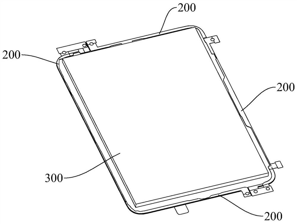
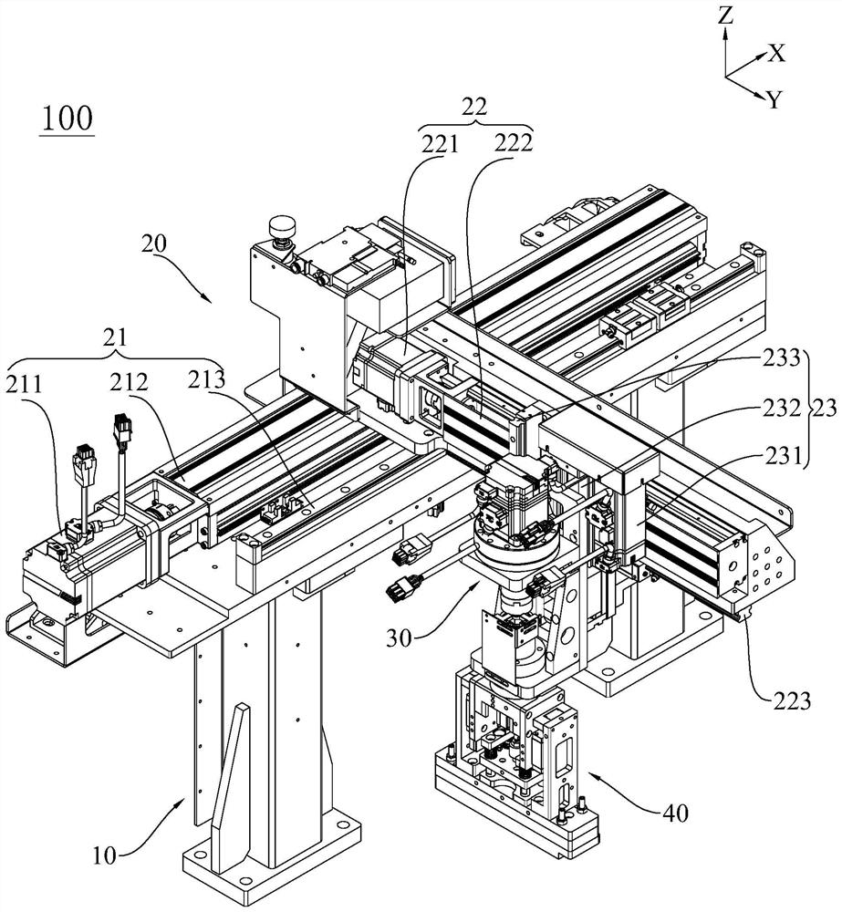
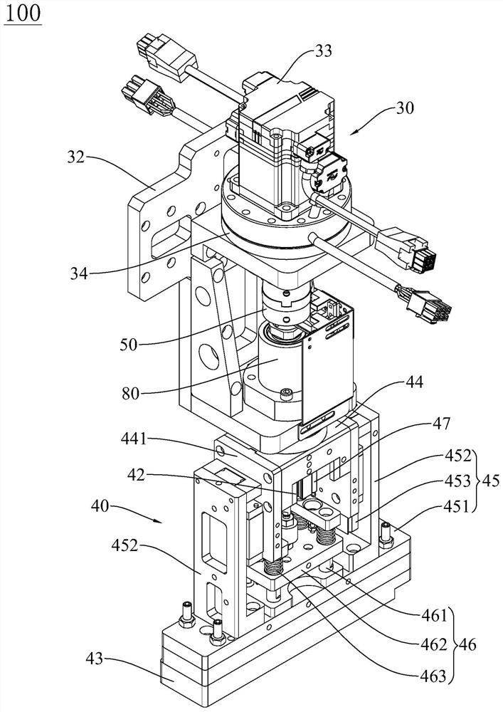
[0023] see Figure 1 to Figure 5 , the present invention provides a placement device 100, which is used to absorb and transfer thin and irregularly shaped adhesive strips 200, so as to paste and assemble them on the workpiece 300. In this application, the adhesive strips 200 are specifically double-sided The noodle strip has a certain degree of elasticity and is in the shape of a strip as a whole. The workpiece 300 is specifically the back cover of the tablet computer. Four adhesive strips 200 need to be mounted on the circumferential edge of the back cover to facilitate the mounting of the screen of the tablet computer. The shapes and sizes of the four rubber strips 200 correspond to the shapes and sizes of the edges around the back cover, and the shapes and si...


PUM


Abstract

The invention discloses a mounting device. The mounting device comprises a transfer mechanism, a rotating mechanism connected to the output end of the transfer mechanism, and a mounting head connected to the output end of the rotating mechanism. The mounting head comprises a rotating shaft with a certain length, a pressing driver connected to the relative lower end of the rotating shaft and a vacuum chuck connected to the output end of the pressing driver, the relative upper end of the rotating shaft is connected with the output shaft of the rotating mechanism through a coupler, and the upper and lower opposite ends of the rotating shaft are correspondingly sleeved with an upper bearing and a lower bearing; the transfer mechanism is used for driving the mounting head to do linear reciprocating motion in the X-axis direction, the Y-axis direction and the Z-axis direction, so that the vacuum chuck can suck and transfer the adhesive tape so as to preliminarily attach the adhesive tape to a workpiece, and the rotating mechanism is used for driving the vacuum chuck to rotate by a certain angle; and the pressing driver is used for driving the vacuum chuck to abut against the adhesive tape preliminarily attached to the workpiece, so that the vacuum chuck and the adhesive tape can be tightly attached, and the pasting device is simple in structure and accurate and efficient in pasting and positioning.

Description

technical field [0001] The invention relates to the field of electronic product manufacturing, in particular to a mounting device. Background technique [0002] With the rapid development of science and technology, people have higher and higher requirements for the quality of electronic products such as mobile phones, tablet computers, earphones, etc. While demanding high quality, they also pursue a design-like appearance. Therefore, more and more electronic products are designed to be smaller, lighter, thinner and have a certain curvature. Therefore, electronic products are developing towards high-density integration and ultra-fine. Correspondingly, the requirements for assembly equipment of electronic products are also increasing. higher. [0003] Especially in the production process of tablet computers, in order to facilitate the assembly of the back cover and the screen, it is often necessary to attach adhesive strips to the edge of the back cover, which involves accura...

Claims


Application Information

Patent Timeline
Patent Type & Authority Applications(China)
IPC IPC(8): H05K13/02H05K13/04B65H5/22
CPCH05K13/02H05K13/0409B65H5/222B65H2701/19
Inventor 张华礼邓春华周成超徐炜晋陈迪勇
Owner DONGGUAN WORLD PRECISION MACHINERY
Learn More