
Skid-mounted type heat energy circulation combination device

A combined device and skid-mounted technology, which is applied in the direction of distribution devices, household refrigeration devices, special distribution devices, etc., can solve the problems of not being particularly convenient, unable to fully utilize waste heat, and low utilization rate of waste heat, so as to achieve convenient transportation and avoid purification Incomplete, good heat preservation effect

Pending Publication Date: 2018-08-24
TIANJIN ZHENGFANG TECH DEV
View PDF0 Cites 0 Cited by
  • Summary
  • Abstract
  • Description
  • Claims
  • Application Information

AI Technical Summary

Problems solved by technology

With the development and progress of society, it is of great significance to pay attention to the utilization technology of circulating water heat energy in real life. At this stage, various enterprises, especially chemical product production enterprises and energy development enterprises, are very important for the reuse of heat energy cycle. It is far larger than that of other enterprises. At present, waste heat reuse uses heat generators or heat pumps for heat exchange, and then uses waste heat in the production process. However, this kind of one-time recycling does not have a high utilization rate of waste heat. It can't give full play to the role of waste heat, and often wastes the waste heat energy that can be developed and utilized, and most of the recycling devices also use sporadic connection, which is very important for the maintenance during installation and later use It is not particularly convenient, how to improve these technical defects and enhance the reuse of heat energy is a problem worthy of discussion and improvement

Method used


Image

  • Skid-mounted type heat energy circulation combination device
  • Skid-mounted type heat energy circulation combination device
  • Skid-mounted type heat energy circulation combination device

Examples


Embodiment Construction

[0027] The specific implementation manners of the present invention will be briefly described below in conjunction with the accompanying drawings.

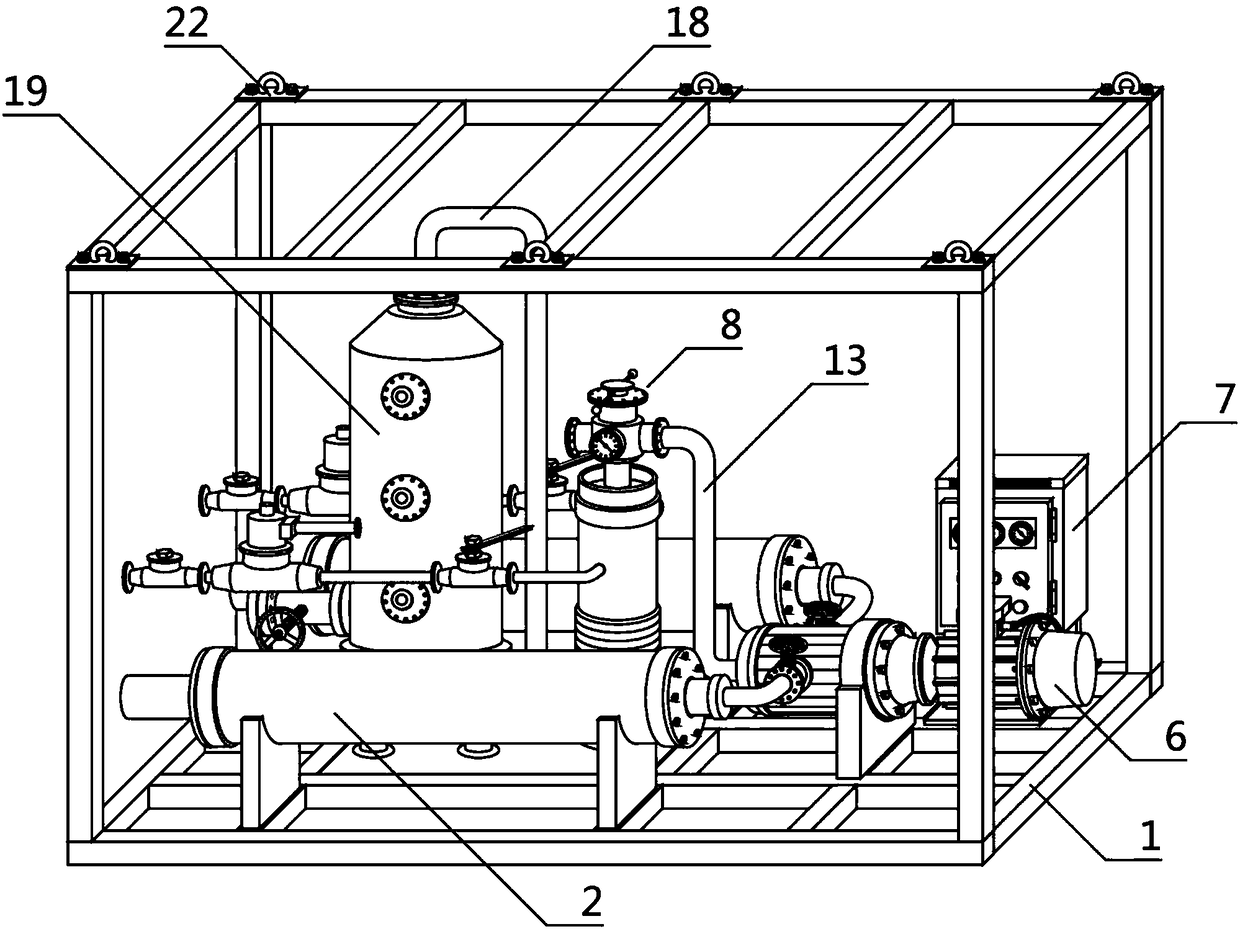
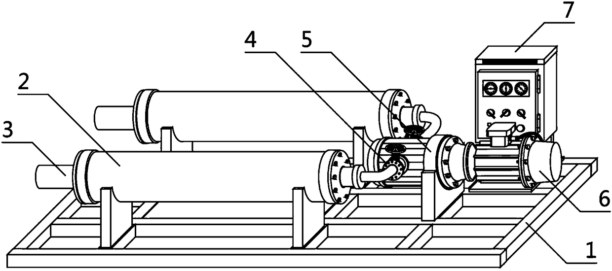
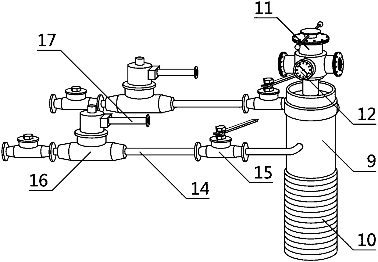
[0028] Such as figure 1 , figure 2 , image 3 , Figure 4A skid-mounted thermal energy cycle combination device is shown, which is characterized in that: a skid-mounted frame 1, several thermal insulation buffer tanks 2, a pressurized pump 5, a control box 7, a filter 8, a purification input pipe 13, and a purification output pipe 18 and a constant temperature storage tank 19, any of the thermal insulation buffer tanks 2 is located inside the skid-mounted frame 1, and the thermal insulation buffer tank 2 is fixedly connected to the skid-mounted frame 1, and any of the thermal insulation buffer tanks 2 is also equipped with The liquid pipeline 3 and the incoming liquid delivery valve 4, the incoming liquid pipeline 3 is located at one side of the thermal insulation buffer tank 2, the incoming liquid pipeline 3 is fixedly connec...


PUM


Abstract

The invention aims to provide a skid-mounted type heat energy circulation combination device. According to the technical scheme, the skid-mounted type heat energy circulation combination device comprises a skid-mounted frame, two insulation buffer tanks, a booster pump, a control box, a filter, a purification input pipe, a purification output pipe and a constant-temperature storage tank. Each insulation buffer tank is provided with a liquid coming pipeline and a liquid coming conveying valve. The filter comprises a sewage accumulation tank, a purification storage tank, a liquid coming purification valve and two sewage discharge pipes. The skid-mounted frame is provided with a plurality of hanging rings. The mechanism is a combination device, skid-mounted type structural design is adopted,overall circulation mechanism transport, packaging and installation can be convenient, insulation of liquid heat can be conducted effectively, purification filtration is conducted, quality of the liquid heat energy is ensured, and heat energy circulation and recycling are achieved. The whole skid-mounted type heat energy circulation combination device is clear in structural thinking, simple and convenient to operate, full-sealed type structural design is adopted, thus the circulation effect is better, environment protection is achieved, service life is long, work efficiency is improved, and operation cost of enterprises is lowered.

Description

technical field [0001] The invention relates to the field of waste heat circulation, in particular to a skid-mounted thermal energy circulation combined device. Background technique [0002] So far, not only in our country, but also in countries all over the world, the technology for thermal energy utilization, whether it is the traditional gas thermal cycle or the current liquid thermal cycle, converts thermal energy into mechanical energy that can be used by factories, and then the mechanical energy Converted into electric energy or other power energy, this cycle can achieve its own long-term stable operation through repeated cycles. With the development and progress of society, it is of great significance to pay attention to the utilization technology of circulating water heat energy in real life. At this stage, various enterprises, especially chemical product production enterprises and energy development enterprises, are very important for the reuse of heat energy cycle....

Claims


Application Information

Patent Timeline
Patent Type & Authority Applications(China)
IPC IPC(8): B67D7/02B67D7/78B67D7/76B01D29/56B65D81/38B65D25/54B67D7/84
CPCB01D29/56B65D25/54B65D81/3806B67D7/02B67D7/76B67D7/78B67D7/84B67D2210/0001
Inventor 李艺金鑫韩霞孙文兰文沙金书芳
Owner TIANJIN ZHENGFANG TECH DEV
Learn More