Defect detection method of underground diaphragm wall based on partitioned ultrasonic tomography

An underground diaphragm wall and defect detection technology, which is applied in the test of basic structure, basic structure engineering, construction, etc., can solve the problems of fracture, blockage, small data volume, etc., achieve wide data coverage, improve detection efficiency, and collect data volume big effect

Active Publication Date: 2019-11-19
DALIAN UNIV OF TECH
View PDF6 Cites 0 Cited by
  • Summary
  • Abstract
  • Description
  • Claims
  • Application Information

AI Technical Summary

Problems solved by technology

However, the limitations of this method are as follows: firstly, during the burying of the acoustic tube, the concrete pouring of the underground diaphragm wall may easily cause the acoustic tube pre-fixed on the steel cage to be bent, deformed, blocked or even broken, resulting in the inability of the ultrasonic probe to enter; secondly, the ultrasonic The measurement can only be carried out in the pre-buried acoustic tube, and the amount of data is relatively small, which affects the accuracy of defect discrimination; finally, the ultrasonic probe transmits and receives signals in the acoustic tube, usually using water in the acoustic tube as a coupling agent, but water The difference in properties with concrete will cause ultrasonic waves to reflect at the interface, weaken the energy entering the underground continuous wall, and affect the detection depth of ultrasonic waves in concrete

Method used


Image

  • Defect detection method of underground diaphragm wall based on partitioned ultrasonic tomography
  • Defect detection method of underground diaphragm wall based on partitioned ultrasonic tomography

Examples


Embodiment Construction

[0015] The specific implementation manners of the present invention will be further described below in conjunction with the accompanying drawings and technical solutions.

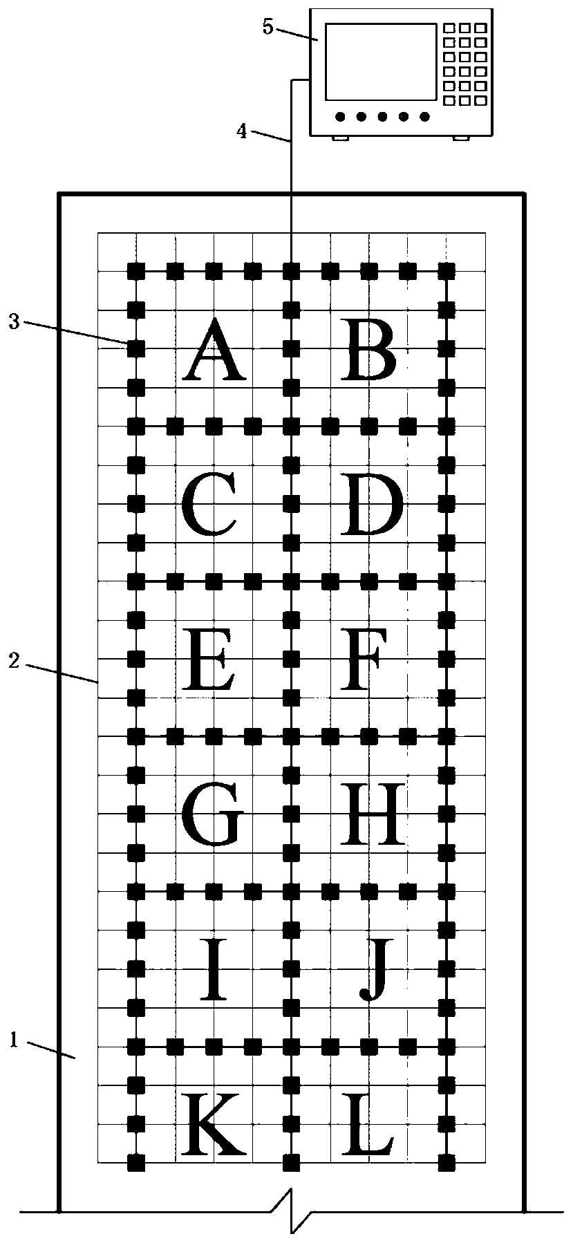
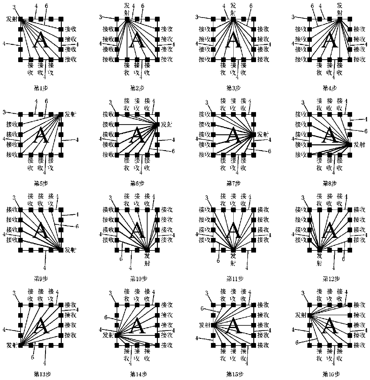
[0016] refer to Figure 1-2 The method for detecting defects in an underground diaphragm wall based on subregional ultrasonic tomography provided in this embodiment includes the following steps:

[0017] (1) Divide the underground diaphragm wall 1 to be poured into grid-like rectangular detection areas, and number these rectangular areas as A, B, C, etc., and the size of the rectangular areas is comprehensively determined according to the ultrasonic penetration ability and the size of the underground diaphragm wall.

[0018] (2) After the reinforcement cage 2 of the underground diaphragm wall 1 is bound, several ultrasonic sensors 3 are arranged on the edge of the reinforcement cage 2 corresponding to the rectangular area divided in (1). These ultrasonic sensors 3 are located in the middle thickness plane ...


PUM


Abstract

The invention provides an underground diaphragm wall flaw detection method based on zoned ultrasonic tomographic imaging. A to-be-poured underground diaphragm wall is divided into latticed rectangulardetection zones, ultrasonic sensors are arranged along the edges of all the rectangular detection zones and fixed to the corresponding positions of a reinforcement cage, and the ultrasonic sensors are connected with a host computer on the ground through a data line; the reinforcement cage is descended and subjected to concrete pouring, and the underground diaphragm wall is formed; and ultrasonictransmission measurement is conducted between the ultrasonic sensors of each rectangular zone, sonic time data are recorded, sonic time is subjected to tomographic imaging after measurement is completed, sound speed distribution in the underground diaphragm wall is obtained, and specific distribution of flaws in the underground diaphragm wall is obtained through sound speed analysis. Measuring pipes do not need to be buried in the underground diaphragm wall, and no adverse effect is caused to the underground diaphragm wall structure; the method is better in coupling performance, and ultrasonicwave attenuation is reduced, and the detection efficiency is improved; and the method is high in collected data volume, wide in data coverage and high in imaging precision.

Description

technical field [0001] The invention belongs to the technical field of underground structure detection, and relates to an underground continuous wall defect detection method based on partitioned ultrasonic tomography. Background technique [0002] With the rapid development of my country's economy and the acceleration of urbanization, in order to meet the growing needs of citizens for travel, rail transit transfer, business, parking, etc., the scale of underground space development is increasing, and the depth of foundation pits is also increasing. deep. These deep and large foundation pits are usually located in the central area of ​​densely populated cities. There are various building structures and traffic arteries on the ground around the foundation pits, and various underground pipelines and subway tunnels are densely covered underground, which makes the surrounding environmental conditions of the foundation pits complex and affects the deformation of the foundation pits...

Claims


Application Information

Patent Timeline
Patent Type & Authority Patents(China)
IPC IPC(8): E02D33/00
CPCE02D33/00
Inventor 覃晖唐玉王峥峥耿铁锁
Owner DALIAN UNIV OF TECH
Why Eureka
Try Eureka