Concrete placing equipment

A material distribution device and concrete technology, which is applied in the processing of building materials, construction, building construction, etc., can solve the problems of hidden safety hazards, large rotational resistance, easy blockage, etc., and achieve the effects of improving flexibility, convenient operation, and improving lift

Inactive Publication Date: 2018-08-24
李晓
View PDF4 Cites 2 Cited by
  • Summary
  • Abstract
  • Description
  • Claims
  • Application Information

AI Technical Summary

Problems solved by technology

The base of the existing concrete placing machine is generally a fixed platform or an inclined leg, which is inconvenient to move. There are also rollers at the lower end of some bases, but the rollers are easy to be touched by mistake, and there are certain safety hazards; There is a rotatable pipeline, but the connection structure between the rotatable pipeline and the fixed pipeline in the prior art is complicated, the rotation resistance is large, and it is easy to block; the height of the concrete placing machine is fixed, and the height cannot be adjusted according to the needs

Method used


Image

  • Concrete placing equipment
  • Concrete placing equipment
  • Concrete placing equipment

Examples


Embodiment 1

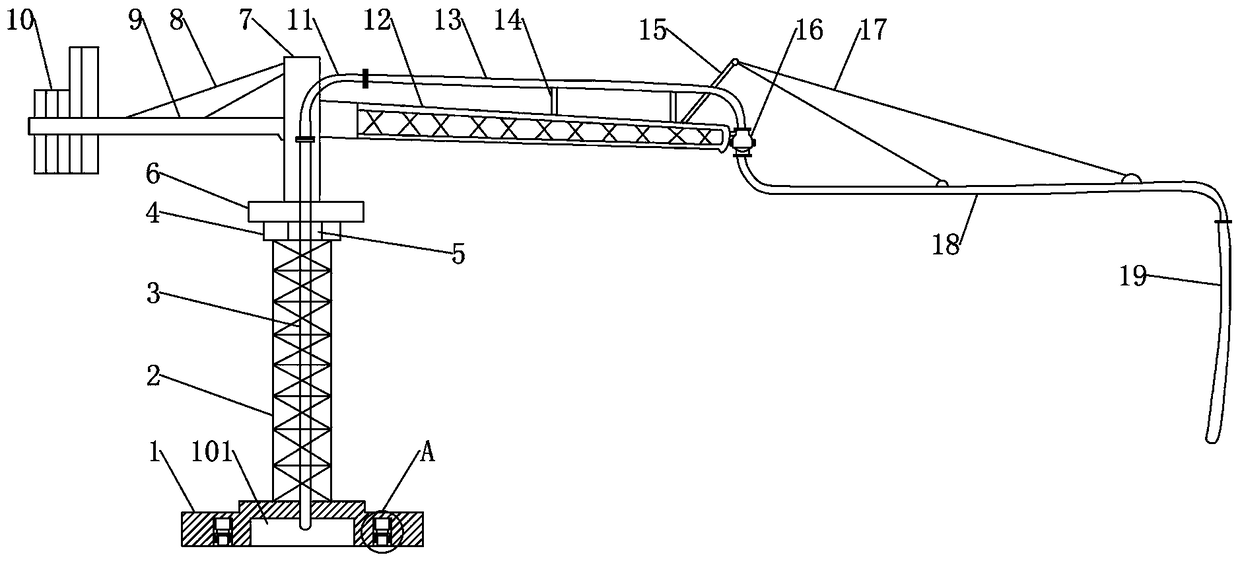
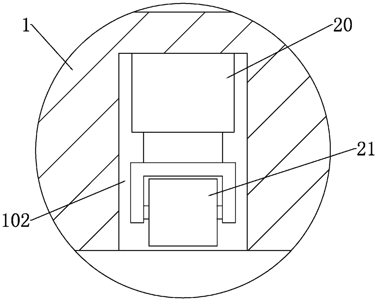
[0019] Embodiment one: if Figure 1-3 As shown, the concrete distributing device includes a base 1, a stand 2, an upper mounting seat 6, a balance arm 9, a main beam 12 and a feeding pipe. Bearing seat 4, a slewing bearing 5 is set in the bearing seat 4, the lower end of the upper mounting seat 6 is set in the slewing bearing 5, the balance arm 9 and the main beam 12 are respectively arranged on both sides of the upper mounting seat 6, and the end of the balance arm 9 A counterweight box 10 is provided. The feeding pipe comprises a standpipe 3, a transverse pipe 13, a rotating pipe 18 and a discharge hose 19, the standpipe 3 is fixedly mounted in the stand 2, the transverse pipe 13 is fixedly installed on the upper end of the balance arm 9, and the standpipe 3 The upper end and the rear end of the transverse pipe 13 are connected through the connecting elbow 11, the front end of the transverse pipe 13 and the rear end of the rotating pipe 18 are rotationally connected through...

Embodiment 2

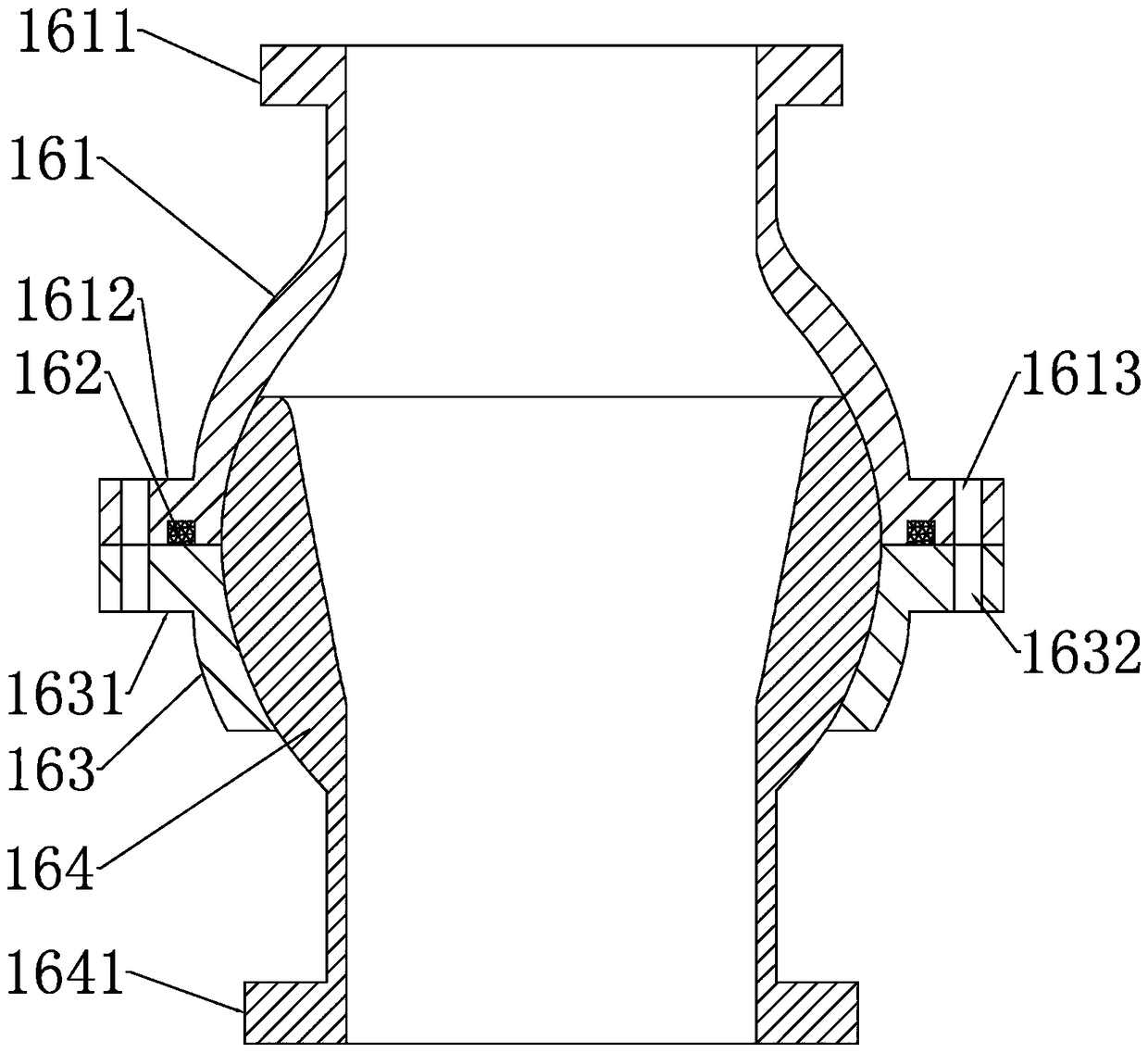
[0022] Embodiment two: see Figure 4 , on the basis of Embodiment 1, in order to further improve the flexibility of the distribution device, the upper end surface of the upper mounting base 6 is provided with an upper mounting base hinged seat 61, and the lower end surface of the main beam 12 is provided with a main beam hinged seat 121. A swing arm hydraulic cylinder 22 is arranged between the hinged seat 61 of the mounting seat and the hinged seat 121 of the main beam. In the beam hinge seat 121; the side wall of the upper support 7 is provided with an upper support hinge seat 71, and the rear end of the main beam 12 is hinged in the upper support hinge seat 71; the connecting elbow 11 is a soft connecting pipe, which can be used Cloth tube. The main beam 12 can swing up and down through the drive of the swing arm hydraulic cylinder 22, which improves the lift of the pipeline, further improves the flexibility of the material distribution device, and is more convenient to us...


PUM


Abstract

The invention discloses concrete placing equipment. The concrete placing equipment comprises a base, a vertical frame is arranged on the upper end surface of the base, a bearing seat is arranged at the upper end of the vertical frame, a pivotal bearing is installed in the bearing seat in a sleeved mode, the lower end of an upper installation seat is installed in the pivotal bearing in a sleeved mode, a balancing arm and a main beam are separately arranged on both sides of the upper installation seat, and a weight box is arranged at the tail end of the balancing arm. A conveying pipe includes avertical pipe, a transverse pipe, a rotary pipe and a discharge hose which are connected in sequence. A roller installing cavity is formed in the lower end surface of the base, roller drive hydrauliccylinders and rolling wheels are arranged in the roller installing cavity, the roller drive hydraulic cylinders are fixedly installed on the top of the roller installing cavity, and the rolling wheels are installed at the lower ends of hydraulic telescopic rods of the roller drive hydraulic cylinders. The roller drive hydraulic cylinders and the rolling wheels are arranged, the rolling wheels aredriven by the roller drive hydraulic cylinders to move up and down, when a placing device needs to move, the rolling wheels are pushed out, when the placing device is not needed, the rolling wheels are installed in the roller installing cavity, the structure is simple, and the use is convenient.

Description

technical field [0001] The invention belongs to the technical field of concrete pumping equipment, in particular to a concrete distributing device. Background technique [0002] The concrete placing machine is the terminal equipment for pumping concrete, and its function is to send the pumped concrete through the pipeline to the formwork of the component to be poured. In order to realize the pouring of the shear wall, the placing machine needs to be placed on the platform, so that the placing machine is located above the shear wall to facilitate the pouring of the shear wall. The base of the existing concrete placing machine is generally a fixed platform or an inclined leg, which is inconvenient to move. There are also rollers at the lower end of some bases, but the rollers are easy to be touched by mistake, and there are certain safety hazards; There is a rotatable pipeline, but the connection structure between the rotatable pipeline and the fixed pipeline in the prior art...

Claims


Application Information

Patent Timeline
Patent Type & Authority Applications(China)
IPC IPC(8): E04G21/04
Inventor 李晓李瑞江
Owner 李晓
Why Eureka
Try Eureka