Electromagnetic double-mode type vibration absorber for transmission shaft

A vibration absorber and drive shaft technology, applied in the directions of magnetic springs, springs/shock absorbers, springs, etc., can solve the problems of reducing the durability of the drive shaft and the wear durability of the drive shaft assembly, so as to avoid wear and durability problems. , fast response, energy-saving adsorption effect

Pending Publication Date: 2018-08-24
SOUTH CHINA UNIV OF TECH
View PDF0 Cites 2 Cited by
  • Summary
  • Abstract
  • Description
  • Claims
  • Application Information

AI Technical Summary

Problems solved by technology

However, this method still has the following disadvantages: Since the natural frequency of the hollow shaft is proportional to the square root of the sum of the inner and outer diameters of the hollow shaft, increasing the inner diameter of the hollow shaft will reduce the durability of the transmission shaft
[0006] In summary, although the above method can solve the resonance problem of the drive shaft assembly under the excitation force of the engine, it will cause other problems, such as the second-order resonance of the drive shaft assembly under the high-frequency excitation force by adding a dynamic vibration absorber problems, as well as wear and durability issues of the drive shaft assembly caused by the use of segmented shafts and hollow shafts
Moreover, it can only solve the resonance problem of the drive shaft assembly under the excitation force of a specific and narrow frequency band

Method used


Image

  • Electromagnetic double-mode type vibration absorber for transmission shaft
  • Electromagnetic double-mode type vibration absorber for transmission shaft
  • Electromagnetic double-mode type vibration absorber for transmission shaft

Examples


Embodiment Construction

[0029] The present invention will be further described in detail below in conjunction with the accompanying drawings and specific embodiments.

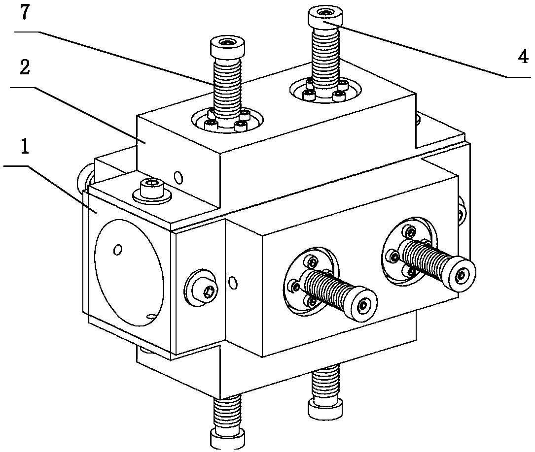
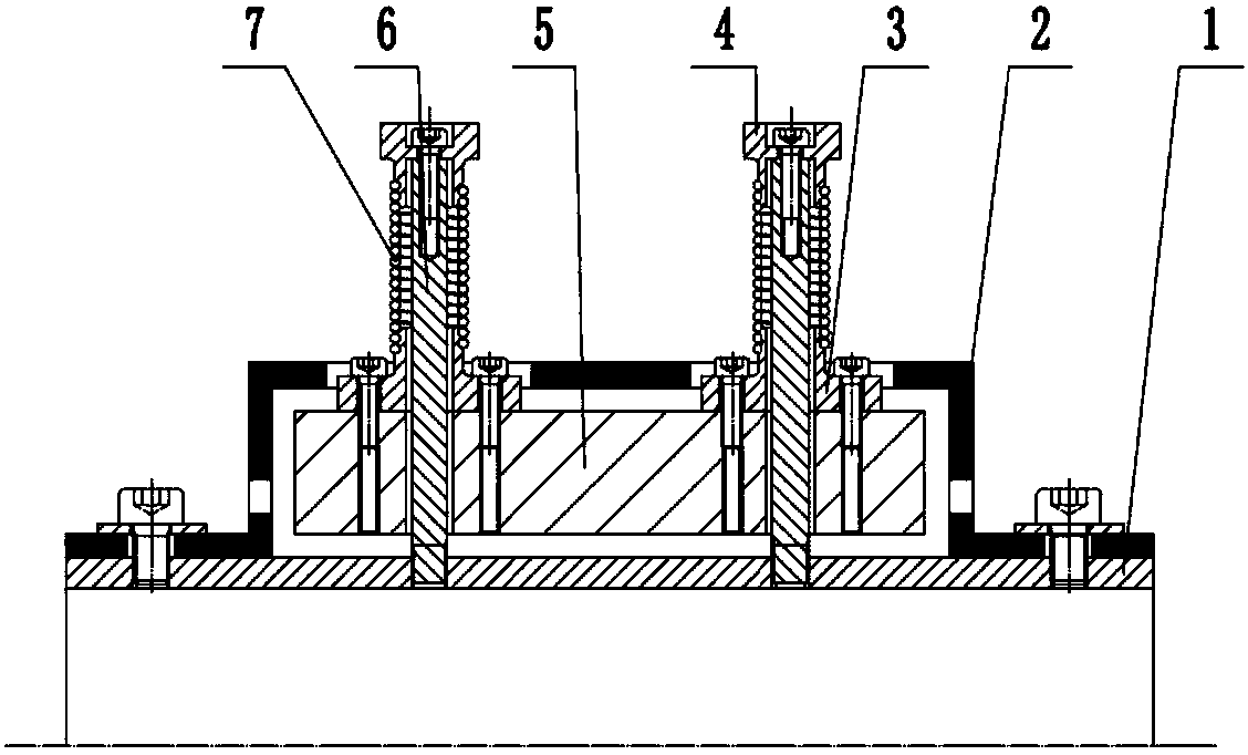
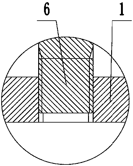
[0030] like figure 1 and figure 2 As shown, a transmission shaft electromagnetic dual-mode shock absorber includes a cubic metal sleeve 1 with a central hole, and four symmetrically fixed four outer walls on the upper, lower, left and right outer walls of the metal sleeve 1. An electromagnetic vibration absorber mode conversion unit, the metal sleeve 1 is directly set on the transmission shaft, and the electromagnetic vibration absorber mode conversion unit is connected with the ECU circuit, and is used for real-time The electromagnet is switched on and off, so that the electromagnetic vibration absorber mode conversion unit is switched between the dynamic vibration absorber mode and the mass block mode.

[0031] like figure 2 As shown, the electromagnetic vibration absorber mode conversion unit includes an electromagnet 5 and tw...


PUM


Abstract

The invention provides an electromagnetic double-mode type vibration absorber for a transmission shaft. The electromagnetic double-mode type vibration absorber for the transmission shaft comprises a cubical metal sleeve which his provided with a round center hole, and four electromagnetic vibration absorber mode switching units which are symmetrically fixedly arranged on the upper outer wall, thelower outer wall, the left outer wall and the right outer wall of the metal sleeve, wherein the electromagnetic vibration absorber mode switching units are connected to an ECU circuit (Electronic Control Unit) and are used for supplying power or cutting off power supply of an electromagnet based on the transmission shaft vibration frequency acquired by the ECU, so that the electromagnetic vibration absorber mode switching units can be switched between a kinetic vibration absorber mode and a mass block mode. Compared with a traditional transmission shaft vibration absorbing method, the electromagnetic double-mode type vibration absorber for a transmission shaft has the advantages that the problem of resonance of a transmission shaft under high- and low-frequency exciting can be synchronously solved; and meanwhile, the durability of the transmission shaft is not influenced while solving the resonance problem of the transmission shaft. The electromagnetic double-mode type vibration absorber for the transmission shaft has the advantages of being fast to respond, energy saving, and high in adsorbing force.

Description

technical field [0001] The invention belongs to the technical field of mechanical transmission, in particular to an electromagnetic double-mode vibration absorber for a transmission shaft. Background technique [0002] Vibration and noise are important factors that deteriorate the performance of mechanical transmission systems and their surrounding environment. The transmission shaft is one of the important sources of vibration and noise in the mechanical transmission system, mainly including the roaring noise and resonance of the transmission shaft. The mechanism of its generation is: when the frequency of the excitation force of the engine is consistent with the natural frequency of the transmission shaft, it will excite the bending mode of the transmission shaft, which will cause the roaring noise and resonance problems of the above-mentioned transmission, and deteriorate the performance of the mechanical transmission system and its surroundings. [0003] A typical appr...

Claims


Application Information

Patent Timeline
IPC IPC(8): F16F6/00
CPCF16F6/00Y02T10/40
Inventor 邱胤原上官文斌
Owner SOUTH CHINA UNIV OF TECH
Why Eureka
Try Eureka