Characteristic vector phase compensation method based on Arnoldi
A phase compensation and eigenvector technology, applied in the field of inverse synthetic aperture radar, can solve the problem of large amount of calculation, achieve the effect of reducing the amount of calculation, ensuring the estimation performance, and reducing the amount of calculation
- Summary
- Abstract
- Description
- Claims
- Application Information
AI Technical Summary
Problems solved by technology
Method used
Image
Examples
specific Embodiment approach 1
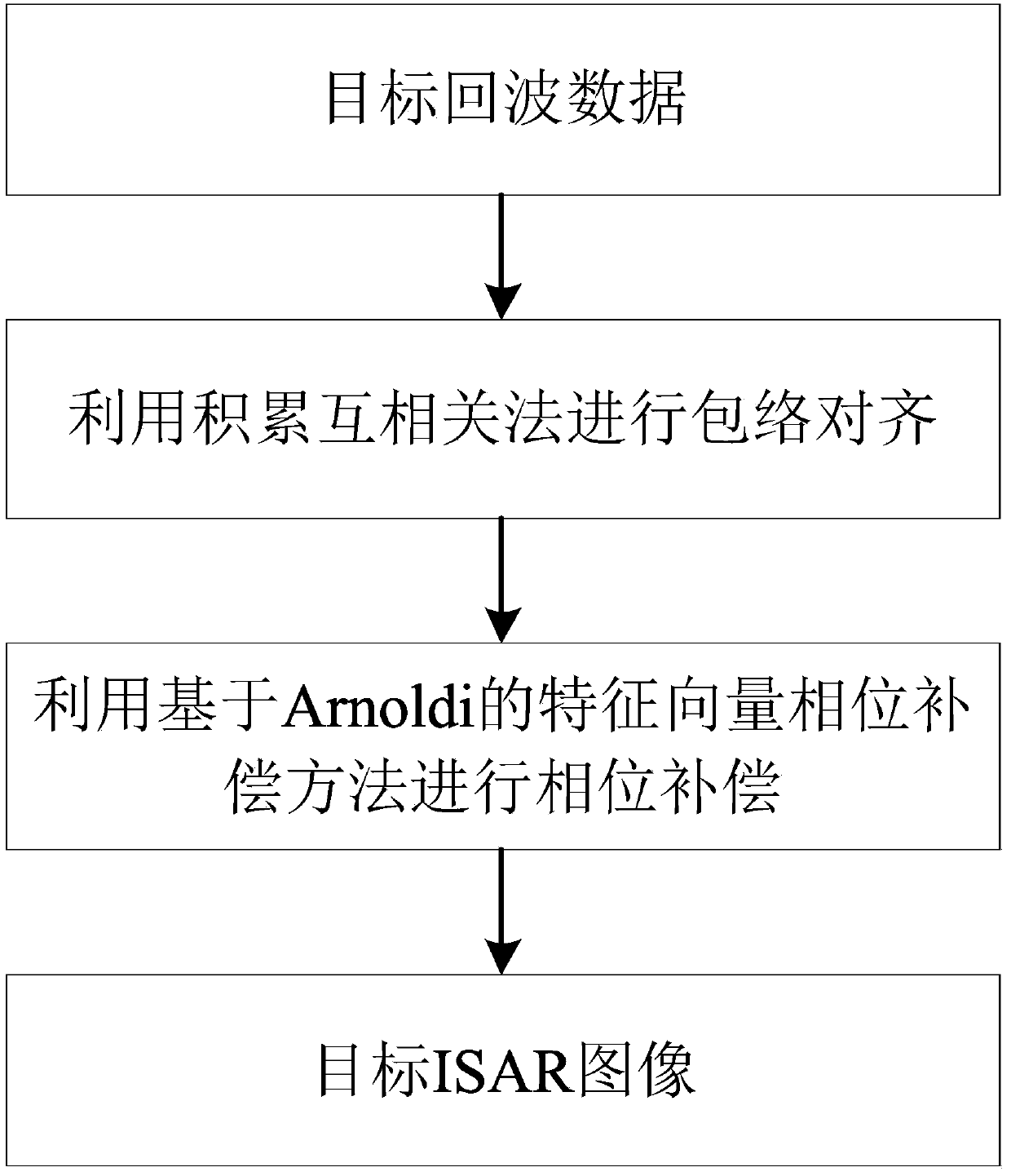
[0016] Specific implementation mode one: combine figure 1 To illustrate this embodiment, the specific process of an Arnoldi-based eigenvector phase compensation method in this embodiment is as follows:
[0017] Step 1: Take M target echoes, the complex range image of the mth target echo distributed along the distance n after range dimension compression is s(m,n), and take a modulo of the complex range image to obtain a target echo dimensional distance image, and use the cumulative cross-correlation method for envelope alignment to obtain the distance dimension compressed data after envelope alignment;
[0018] Among them, 0≤m≤(M-1), 0≤n≤(N-1), M is the number of points in the azimuth direction (that is, the number of target echoes), and N is the number of points in the distance direction;
[0019] Step 2, obtain the sampling covariance matrix according to the distance dimension compressed data after envelope alignment;
[0020] Step 3. Use Arnoldi to iteratively solve the e...
specific Embodiment approach 2
[0024] Specific embodiment 2: The difference between this embodiment and specific embodiment 1 is that in the first step, M target echoes are taken, and the complex range image of the mth target echo distributed along the distance n after distance dimension compression is s(m,n), take the modulus of the complex range image to obtain the one-dimensional range image of the target echo, and use the cumulative cross-correlation method to perform envelope alignment to obtain the range dimension compressed data after envelope alignment; the specific process is:
[0025] Step 11, the complex range image of the m-th target echo distributed along the distance n after the distance dimension compression is expressed as s(m,n);
[0026] Among them, 0≤m≤(M-1), 0≤n≤(N-1), M is the number of points in the azimuth direction (that is, the number of target echoes), N is the number of points in the distance direction, and the values of N and M are positive integers ;
[0027] Steps 1 and 2, t...
specific Embodiment approach 3
[0036] Specific embodiment three: the difference between this embodiment and specific embodiment one or two is: in the step two, the sampling covariance matrix is obtained according to the distance dimension compressed data after the envelope alignment; the specific process is:
[0037] Step 21, the complex envelope s of the distance dimension compressed data of the dth distance unit d Expressed as:
[0038]
[0039] Among them, a d is the scattering rate of the strong scattering point in the dth distance unit, d=1,2,...,N-1, v is the phase error vector, n d is Gaussian white noise, is the phase difference between the e+1th azimuth unit and the first azimuth unit, e=1,2,...,M-1, is an imaginary unit;
[0040] s(m,n) is the complex range image expression of the m-th echo distributed along the distance n after distance dimension compression, 0≤m≤(M-1), 0≤n≤(N-1), so after The echo data compressed in the range dimension is an M×N matrix, each row of the matrix is a ...
PUM
| Property | Measurement | Unit |
|---|---|---|
| Bandwidth | aaaaa | aaaaa |
| Pulse repetition frequency | aaaaa | aaaaa |
Abstract
Description
Claims
Application Information
 - R&D
- Intellectual Property
- Life Sciences
- Materials
- Tech Scout
- Unparalleled Data Quality
- Higher Quality Content
- 60% Fewer Hallucinations
Browse by: Latest US Patents, China's latest patents, Technical Efficacy Thesaurus, Application Domain, Technology Topic, Popular Technical Reports.
© 2025 PatSnap. All rights reserved.Legal|Privacy policy|Modern Slavery Act Transparency Statement|Sitemap|About US| Contact US: help@patsnap.com


