Composite wing optimization design method based on aerodynamic reduced-order model

A reduced-order model, composite material technology, applied in design optimization/simulation, calculation, special data processing applications, etc., can solve the problems of not considering airfoil camber and thickness, low aerodynamic accuracy, etc., to improve efficiency, improve The effect of accuracy

Active Publication Date: 2018-08-24
BEIHANG UNIV
View PDF10 Cites 15 Cited by
  • Summary
  • Abstract
  • Description
  • Claims
  • Application Information

AI Technical Summary

Benefits of technology

This new approach described in this patented describes an improvement on how well complex materials are designed without requiring significant effort from researchers who have been working hard-to-reach areas such as aircraft manufacturing. It uses computational fluid dynamics (CFD) techniques to analyze airflow over wings instead of just analyzing them individually. By comparing these results against simulations, we found that they were more accurate than previous methods but still efficient enough to produce high quality composites. Overall, our technical effect was increased productivity while maintaining good flight characteristics.

Problems solved by technology

This patents discusses how we want to optimize the performance (strength) and durability of wings used on commercial jets by optimizing their structures' characteristics - composites that make up them. However, current designs often result in poor balance between tensile stress and compression strain during flight due to complex geometry shapes involved in the construction processes themselves. To address this issue, there needs to accurately allocate certain parameters based upon the desired results from the optimized design method proposed earlier.

Method used


Image

  • Composite wing optimization design method based on aerodynamic reduced-order model
  • Composite wing optimization design method based on aerodynamic reduced-order model
  • Composite wing optimization design method based on aerodynamic reduced-order model

Examples


Embodiment Construction

[0021] The present invention will be further described in detail with reference to the accompanying drawings and embodiments.

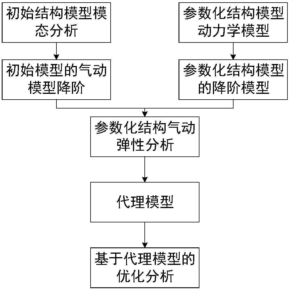
[0022] figure 1 These are the overall steps of the composite material wing optimization design method based on the aerodynamic reduced-order model of the present invention, and each implementation step is described in detail below.

[0023] Step 1: Establish the structural finite element model of the initial reference wing (ie, the initial reference model), and obtain the mode Φ of the structural model through modal analysis, including the frequency and mode shape of the mode.

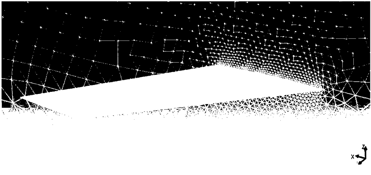
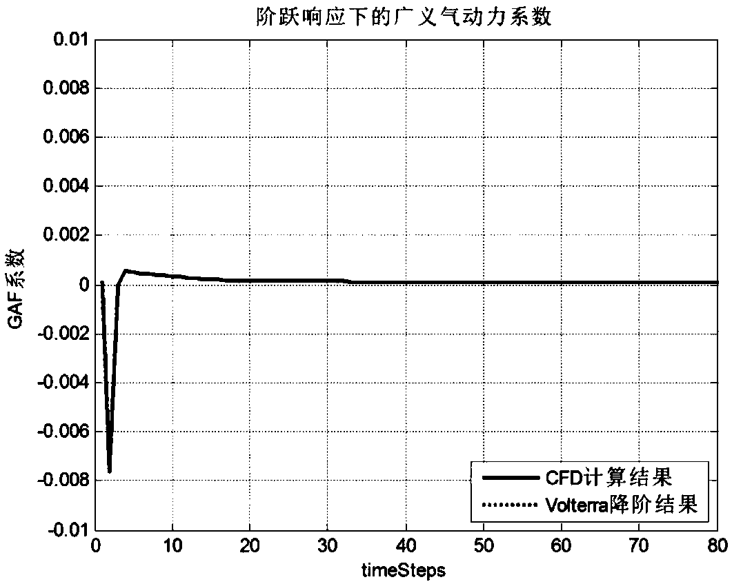
[0024] Step 2, use CFD to calculate the aerodynamic force, and establish the aerodynamic model of the initial reference model. The modal Φ of the finite element model of the reference model is used, and the step signals of the mode shapes of each order are taken as input to obtain the aerodynamic response in the corresponding mode.

[0025] As it is done in the step response...


PUM


Abstract

The invention provides a composite wing optimization design method based on an aerodynamic reduced-order model, and belongs to the technical field of aircraft design. Firstly, a structural model and an aerodynamic model of a reference model are established, and modalities of a finite-element model of the reference model are adopted to obtain the corresponding aerodynamic reduced-order model; modalities of the reference model are used as hypothetical modalities to obtain a reduced-order model of the parametric finite-element model; then aeroelastic analysis of the parametric model is carried out; thickness and an angle of composite ply are used as design variables for experiment design, and the design variables obtained by experiment design are used as input and aeroelastic analysis is usedas output to obtain an agent model of the parametric model; and optimization design of a composite wing is carried out on the basis of the agent model. The method improves accuracy of aeroelastic analysis of the wing, improves efficiency of analysis, and is suitable for use in optimization calculation on composite structure design to facilitate obtaining of a composite wing structure with betterperformance.

Description


Claims


Application Information

Patent Timeline
Owner BEIHANG UNIV
Why Eureka
Try Eureka