Wet chain type etching groove liquid inlet structure

A technology for etching grooves and feeding liquid, which is applied in the direction of sustainable manufacturing/processing, climate sustainability, semiconductor devices, etc. It can solve problems such as slime and silicon wafer degradation, achieve uniform liquid feeding, stable liquid level, and increase process The effect of debugging stability

Pending Publication Date: 2018-08-24
WUXI SUNTECH POWER CO LTD
View PDF0 Cites 0 Cited by
  • Summary
  • Abstract
  • Description
  • Claims
  • Application Information

AI Technical Summary

Problems solved by technology

The above-mentioned wet etching tank mainly has the following defects: the liquid flows out from the liquid outlet hole 6a on the liquid inlet pipe 5a, the tube easily accumulates gas and flows out from the liquid outlet hole 6a, and when the silicon wafer is walking in the etching liquid, the bubbles float out of the liquid. Explosion of the surface will cause mucus on the front side of the silicon wafer, resulting in bubble marks on the surface of the silicon wafer, resulting in the degradation of the silicon wafer or the formation of defective chips

Method used


Image

  • Wet chain type etching groove liquid inlet structure
  • Wet chain type etching groove liquid inlet structure
  • Wet chain type etching groove liquid inlet structure

Examples


Embodiment 1

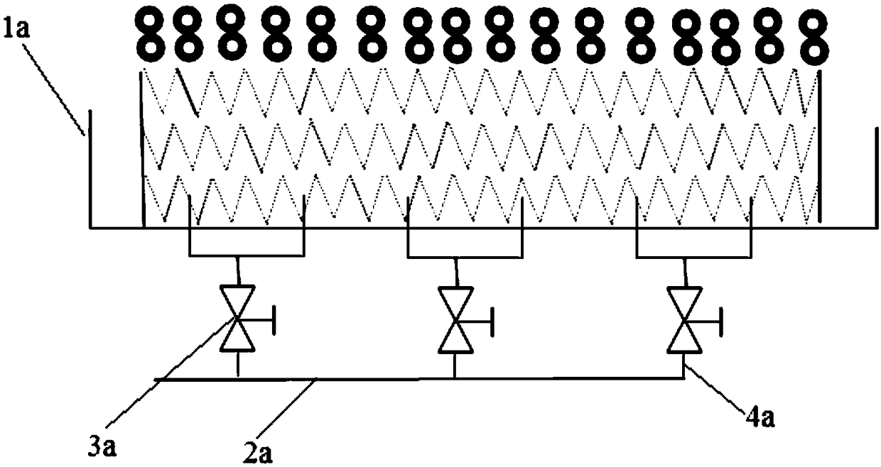
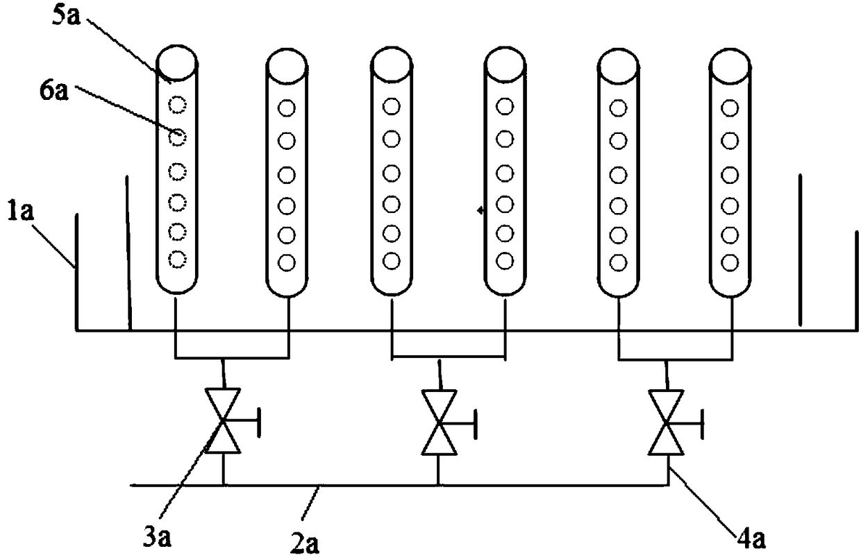
[0027] like figure 2 , image 3 As shown, the liquid inlet structure of the wet chain etching tank according to the present invention includes a liquid inlet box 2 arranged at the bottom of the wet etching tank body 1, and the liquid inlet box 2 is arranged on a side away from the feeding direction of the silicon wafer; Pic 4-1 , Figure 4-2 , Figure 4-3 As shown, a liquid discharge hole 3 is arranged on the side of the liquid inlet box 2 facing the feeding direction of silicon wafers, and an inner lining plate 4 is arranged inside the liquid inlet box 2, and the bottom of the inner lining plate 4 is connected with the liquid inlet The lower part of the box 2 is sealed and connected, and there is a liquid outlet gap 5 between the top of the inner lining plate 4 and the upper part of the liquid inlet box 2; the bottom of the liquid inlet box 2 is provided with a liquid inlet 6, and the liquid inlet box 2 passes through the liquid inlet 6 is connected with the liquid inlet...

Embodiment 2

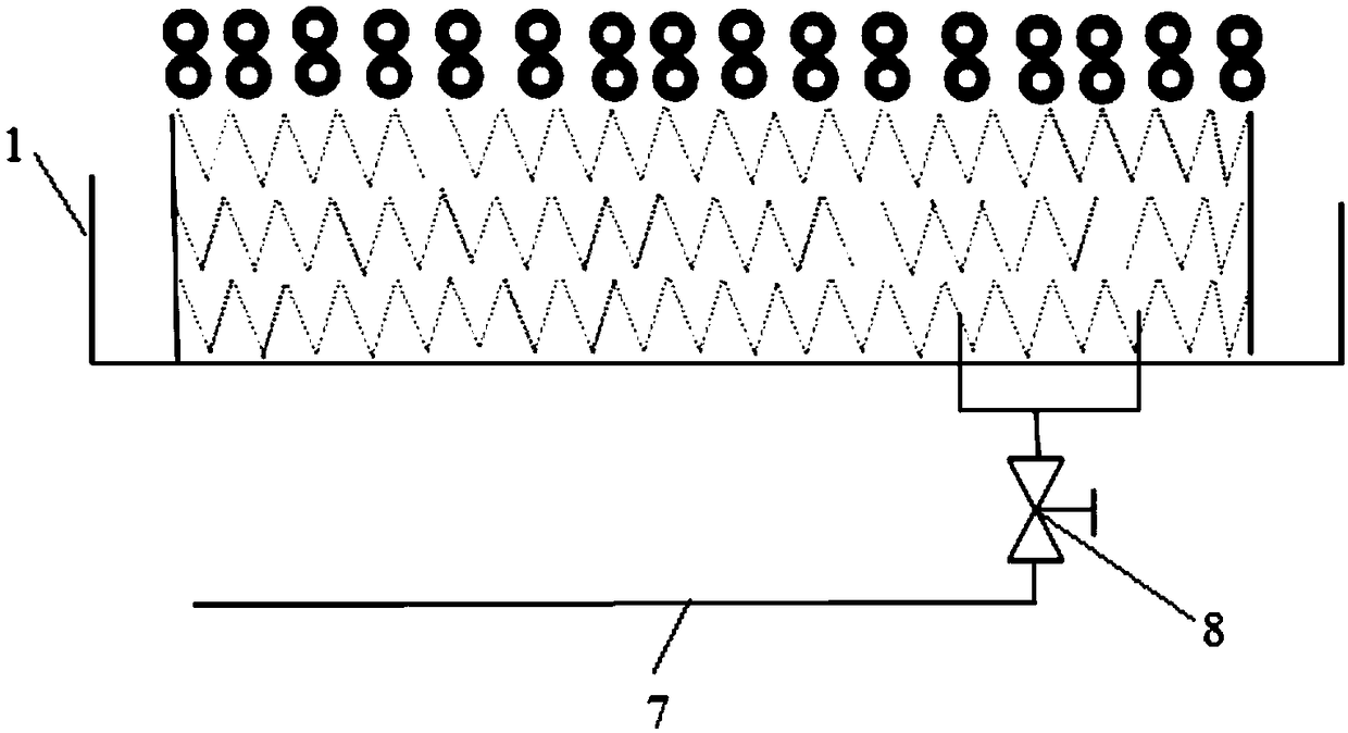
[0032] The liquid inlet structure of the wet chain etching tank of the present invention includes a liquid inlet box 2 arranged at the bottom of the wet etching tank body 1, and the liquid inlet box 2 is arranged on a side away from the feeding direction of the silicon wafer; The side of the liquid box 2 facing the feeding direction of the silicon wafer is provided with two or more rows of liquid discharge holes 3, and an inner lining plate 4 is arranged inside the liquid inlet box 2, and the bottom of the inner lining plate 4 is in contact with the liquid inlet. The lower part of the box 2 is sealed and connected, and there is a liquid outlet gap 5 between the top of the inner lining plate 4 and the upper part of the liquid inlet box 2; the bottom of the liquid inlet box 2 is provided with a liquid inlet 6, and the liquid inlet box 2 passes through the liquid inlet 6 is connected with the liquid inlet pipeline 7 to realize liquid inlet; a valve body 8 is arranged on the liquid...

Embodiment 3

[0037] The liquid inlet structure of the wet chain etching tank of the present invention includes a liquid inlet box 2 arranged at the bottom of the wet etching tank body 1, and the liquid inlet box 2 is arranged on a side away from the feeding direction of the silicon wafer; The side of the liquid box 2 facing the feeding direction of the silicon wafer is provided with two or more rows of liquid discharge holes 3, and an inner lining plate 4 is arranged inside the liquid inlet box 2, and the bottom of the inner lining plate 4 is in contact with the liquid inlet. The lower part of the box 2 is sealed and connected, and there is a liquid outlet gap 5 between the top of the inner lining plate 4 and the upper part of the liquid inlet box 2; the bottom of the liquid inlet box 2 is provided with a liquid inlet 6, and the liquid inlet box 2 passes through the liquid inlet 6 is connected with the liquid inlet pipeline 7 to realize liquid inlet; a valve body 8 is arranged on the liquid...


PUM


Abstract

The invention relates to a wet chain type etching groove liquid inlet structure. The wet chain type etching groove liquid inlet structure is characterized by comprising a liquid inlet box arranged atthe bottom of a wet etching groove body; the liquid inlet box is arranged on one side, far from the feeding direction, of a silicon wafer; a row of liquid outlet draining holes are formed in one side,towards the feeding direction of the silicon wafer, of the liquid inlet box; a liquid inlet is formed in the bottom of the liquid inlet box; and the liquid inlet box is connected with a liquid inletpipeline through the liquid inlet. By virtue of the wet chain type etching groove liquid inlet structure, the groove body liquid inlet stability can be improved, generation of air bubbles on the surface of the silicon wafer can be avoided, and generation of unqualified wafers can be reduced or eliminated.

Description

technical field [0001] The invention relates to a solar photovoltaic wet chain etching machine, in particular to a liquid inlet structure for a wet chain etching tank. Background technique [0002] After the PN junction is formed by diffusion in solar cell manufacturing, it is necessary to remove the PN junction on the back and side of the silicon wafer through the etching process to achieve the purpose of insulating the front and back. At present, the following problems exist in the use of solar photovoltaic wet chain etching machines: the wet etching tank of the existing wet light chain etching machines generally uses the liquid inlet pipe to enter the liquid, such as Picture 1-1 , Figure 1-2 As shown, a plurality of liquid inlet pipes 2a are connected to the bottom of the wet etching tank 1a, and the liquid inlet pipes 2a are connected to a plurality of liquid inlet pipe branches 4a through the valve 3a, and the liquid inlet pipe branches 4a are connected to the liquid ...

Claims


Application Information

Patent Timeline
Patent Type & Authority Applications(China)
IPC IPC(8): H01L21/67H01L31/18
CPCH01L21/67075H01L31/1804Y02P70/50
Inventor 陈玉唐麟
Owner WUXI SUNTECH POWER CO LTD
Why Eureka
Try Eureka