Differential feed pattern reconfigurable antenna

A technology of reconstructing antennas and differential feeding, applied in the research field of mobile communication, can solve problems such as unfavorable antenna and RF front-end integration, unoptimistic solutions, and reduced system efficiency, and achieves reduction of RF front-end losses, simple structure, wide The effect of the application foreground

Active Publication Date: 2018-08-24
SOUTH CHINA UNIV OF TECH
View PDF3 Cites 1 Cited by
  • Summary
  • Abstract
  • Description
  • Claims
  • Application Information

AI Technical Summary

Problems solved by technology

However, the use of balun will cause RF front-end loss and reduce system efficiency. The solution is not optimistic, which is not conducive to the integration of antenna and RF front-end

Method used


Image

  • Differential feed pattern reconfigurable antenna
  • Differential feed pattern reconfigurable antenna
  • Differential feed pattern reconfigurable antenna

Examples


Embodiment

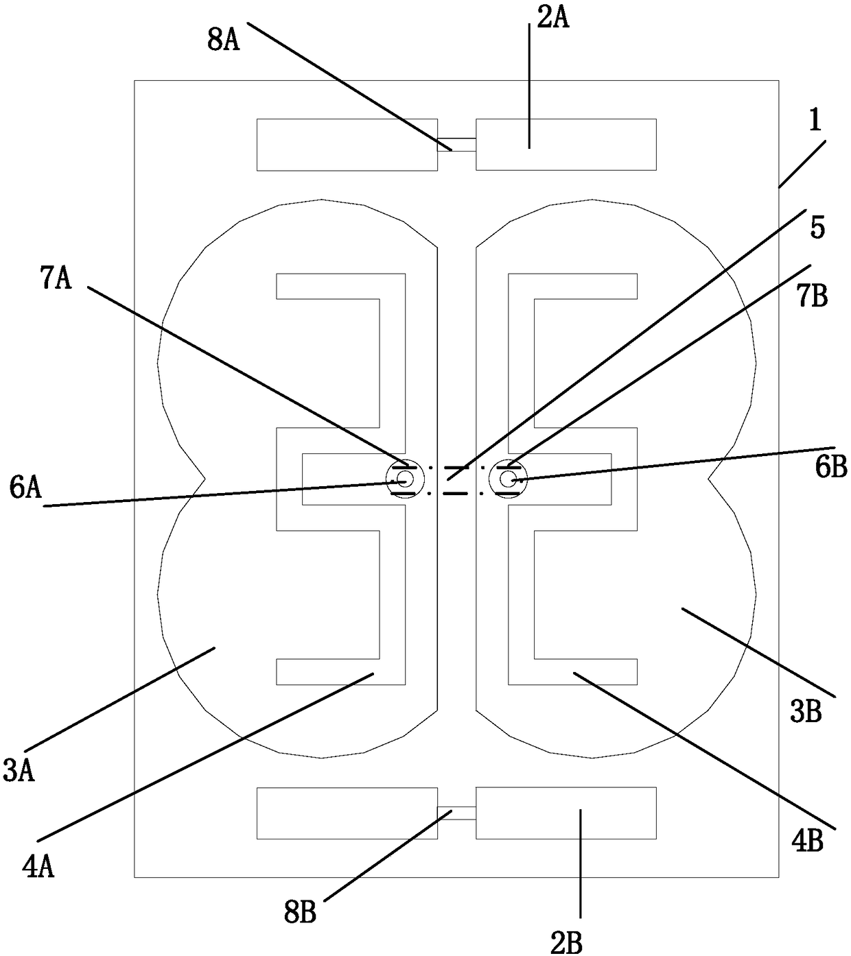
[0044] Such as figure 1 As shown, a reconfigurable antenna with a differential feeding pattern includes a dielectric substrate 1, a microstrip line feeding structure 5, a coaxial feeder unit, an antenna radiation unit, and a parasitic unit;

[0045] The microstrip line feed structure is etched on the back of the dielectric substrate; the coaxial feeder unit is etched on the front of the dielectric substrate; the antenna radiation unit is etched on the front of the dielectric substrate; the parasitic unit is etched on the front of the dielectric substrate; the parasitic unit is at both ends of the antenna radiation unit;

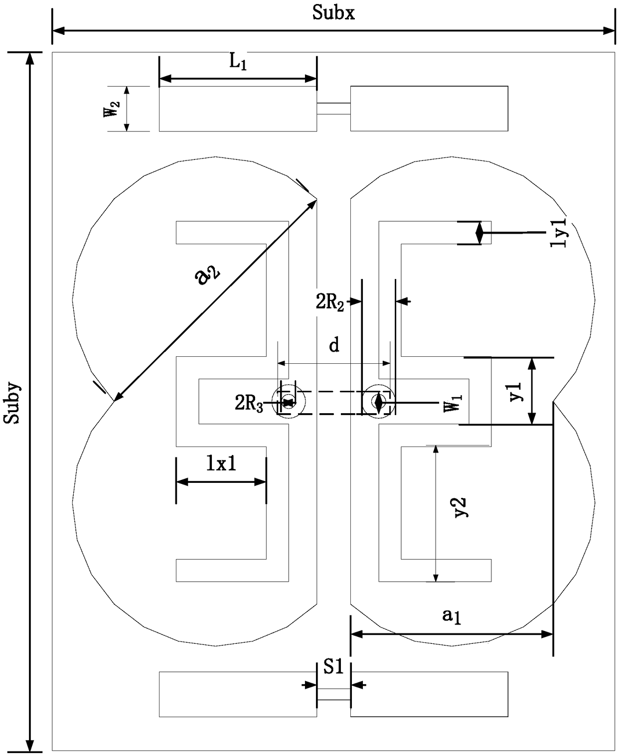
[0046] Such as figure 2 As shown, the length Suby of the dielectric substrate 1 is 62mm, and the width Subx is 50mm; the parasitic units 2A and 2B are composed of two sections of microstrip lines with the same line width W2=4mm, and the length L1 of the microstrip line is 14mm; The minimum width a of sub 3A, 3B 1 18mm, Each parameter of U-shaped slot 4A,...


PUM


Abstract

The invention discloses a differential feed pattern reconfigurable antenna, which comprises a dielectric substrate, a microstrip feed structure, a coaxial feed line unit, an antenna radiation unit anda parasitic unit, wherein the back surface of the dielectric substrate is etched with the microstrip feed structure for feeding the antenna; the front surface of the dielectric substrate is etched with the antenna radiation unit and the parasitic unit; the antenna radiation unit has a planar structure and comprises a first dipole and a second dipole which are parallel and are grooved, the first dipole and the second dipole are symmetrical about the center of the dielectric substrate, and the parasitic unit is arranged at two sides of the antenna radiation unit. By adopting a differential feedstructure, integration with a radio frequency front end is facilitated, the size is small, the weight is light, the structure is simple and patterns on an E plane and an H plane are reconfigurable.

Description

technical field [0001] The invention relates to the research field of mobile communication, in particular to a reconfigurable antenna with a differential feeding pattern. Background technique [0002] Antenna is an essential part of wireless communication. With the rapid development of wireless communication technology, antenna technology has also been developed rapidly. In order to reduce the cost of wireless communication systems, compact and highly integrated RF front-end products have become the mainstream of design. In the RF front end, the application of the differential system has significantly improved the performance of the RF transceiver system. [0003] Traditional antennas usually use a single-port feed, and an additional balun or inverting power divider (balanced balun) needs to be connected in the system to realize the conversion between single-ended signals and differential signals. However, the use of balun will cause RF front-end loss and reduce system effi...

Claims


Application Information

Patent Timeline
Patent Type & Authority Applications(China)
IPC IPC(8): H01Q1/38H01Q3/24
CPCH01Q1/38H01Q3/24
Inventor 靳贵平黎淼兰曾广洁
Owner SOUTH CHINA UNIV OF TECH
Why Eureka
Try Eureka