Stereoscopic wall surface flower stand
A three-dimensional, flower stand technology, applied in the directions of container cultivation, horticulture, and botany equipment and methods, can solve problems such as unfavorable installation and large space for flower cultivation, and achieve convenient maintenance, beautiful and firm manufacturing cost and technological level, and easy disassembly. Effect
- Summary
- Abstract
- Description
- Claims
- Application Information
AI Technical Summary
Problems solved by technology
Method used
Image
Examples
Embodiment 1
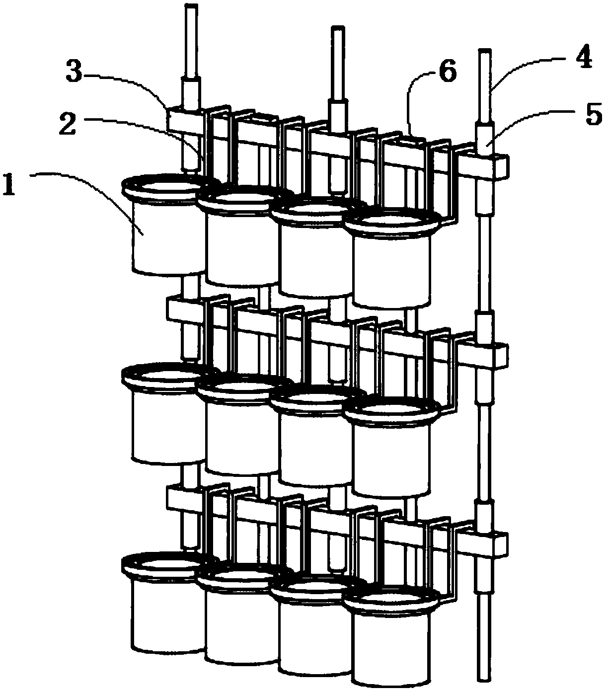
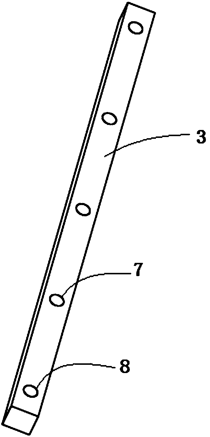
[0029] See Figure 1-Figure 7 , the three-dimensional wall flower stand disclosed in this embodiment includes several crossbars 3, several connecting rods 4, several cup holders 2 and several flower pots 1, and several vertical first through holes 8 are arranged on the crossbars 3, and a The connecting rod 4 passes through the first through holes 8 of several cross bars 3, and the connecting rod 4 is fixed by damping rubber sleeves 5 at the upper and lower ends of the cross bar 3, and several cross bars 3 are connected together by several connecting rods 4 ;See Figure 4 , the cup holder 2 is provided with a hook 9, the cup holder 2 can be hooked on the cross bar 3 through the hook 9, and the flower pot 1 is clamped in the cup holder 2. Specifically, the cup holder 2 includes a cup ring 10 and a hook 9, the cup ring 10 and the hook 9 are formed by bending a metal rod, the two ends of the metal rod are bent to form a hook, and the inner diameter of the hook is the same as the ...
Embodiment 2
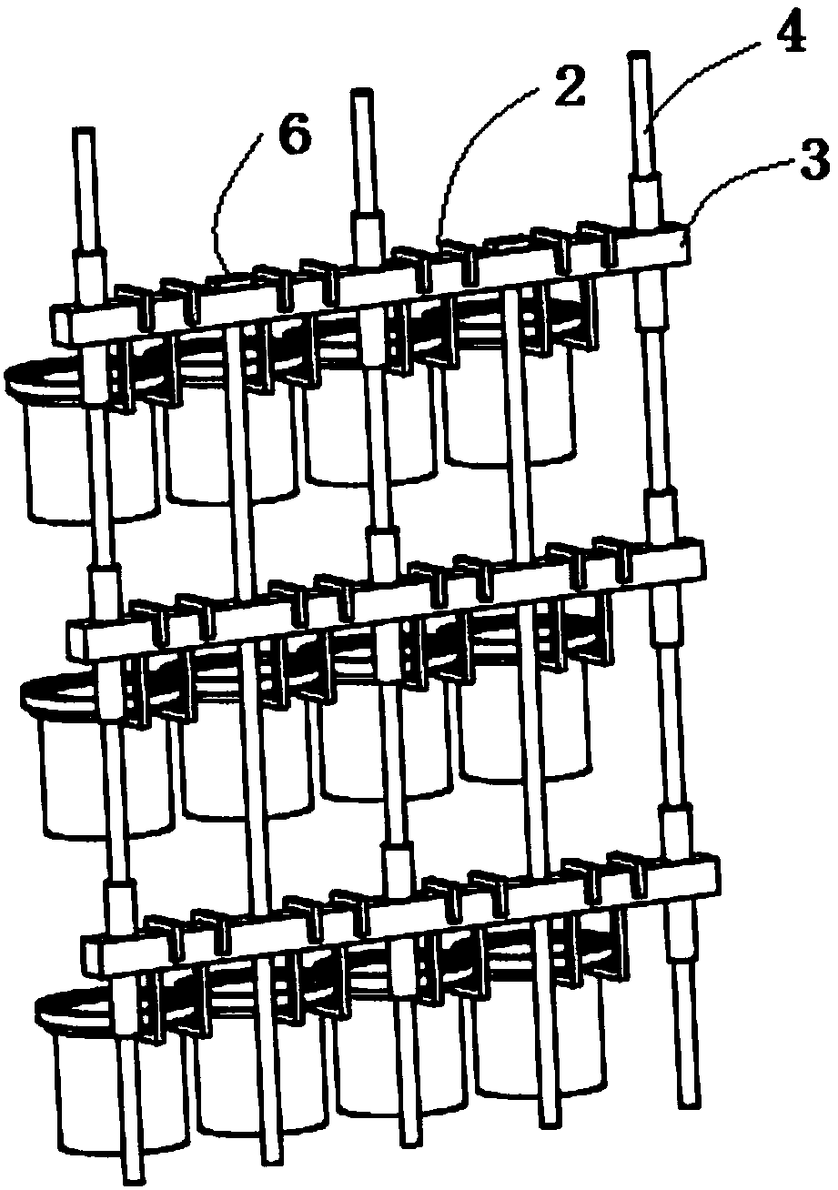
[0034] See image 3 , the technical solution of this embodiment is basically the same as that of Embodiment 1, the only difference is that a reinforcing rod 6 is also provided, the top of the reinforcing rod 6 is provided with a limit block 12, and the cross bar 3 is provided with a second through hole 7, The reinforcing bar 6 is plugged into the second through hole 7 to connect several cross bars 3 in series, and the limiting block 12 is clamped on the upper surface of the uppermost cross bar 3 . The reinforcing rod 6 is a solid cylinder, and the connecting rod 4 is a solid cylinder. Specifically, both the connecting rod 4 and the reinforcing rod 6 are solid cylindrical steel bodies to ensure the facade support strength of the product without being bent. The cross bar 3 is a square structure. The reinforcement rod 6 is designed as a vertical body from top to bottom, which is more firm and the deformation is reduced after installation.
Embodiment 3
[0036] See Figure 7 , the technical solution of this embodiment is basically the same as that of Embodiment 2, the only difference is that the bottom of the connecting rod 4 is provided with a thread 14, the bottom of the connecting rod 14 is provided with a connecting rod extension rod, and the top of the connecting rod extension rod is provided with a screw hole 13 and The connecting rod 14 cooperates, and the bottom of the connecting rod extension rod is provided with thread 14, which cooperates with the connecting rod extension rod below; Reinforcement rod extension rod, the top of the reinforcement rod extension rod is provided with a screw hole to cooperate with the reinforcement rod, and the bottom of the reinforcement rod extension rod is provided with a thread, which cooperates with the reinforcement rod extension rod below, so as to realize the increase or decrease of the scale at will.
PUM
 Abstract
Description
Claims
Application Information
 - R&D
- Intellectual Property
- Life Sciences
- Materials
- Tech Scout
- Unparalleled Data Quality
- Higher Quality Content
- 60% Fewer Hallucinations
Browse by: Latest US Patents, China's latest patents, Technical Efficacy Thesaurus, Application Domain, Technology Topic, Popular Technical Reports.
© 2025 PatSnap. All rights reserved.Legal|Privacy policy|Modern Slavery Act Transparency Statement|Sitemap|About US| Contact US: help@patsnap.com


