Automatic ultrasonic imaging system and method thereof

An ultrasonic imaging system and imaging technology, applied in the direction of ultrasonic/sonic/infrasonic equipment control, ultrasonic/sonic/infrasonic diagnosis, sound wave diagnosis, etc., can solve the problems of ultrasonic imaging automation and intelligentization without a qualitative leap

Inactive Publication Date: 2018-08-28
郝晓辉
View PDF4 Cites 13 Cited by
  • Summary
  • Abstract
  • Description
  • Claims
  • Application Information

AI Technical Summary

Problems solved by technology

This adjustment is relatively simple and easy. However, as mentioned earlier, the ultrasound imaging system has many parameters, far more than just the gain. How to extend this adjustment method to the application of the entire ultrasound imaging system? For traditional ultrasound imaging equipment based on It becomes an unrealizable luxury for a one-way system architecture in which the doctor's parameters are adjusted for imaging.
Therefore, although leading companies in the field of ultrasound have begun to expand the market in the direction of intelligent ultrasound imaging, and are committed to rapidly expanding ultrasound imaging technology to emerging clinical application fields outside of ultrasound diagnostics and non-central urban areas in developing countries, the development of ultrasound imaging There is still no qualitative leap in automation and intelligence

Method used


Image

  • Automatic ultrasonic imaging system and method thereof
  • Automatic ultrasonic imaging system and method thereof
  • Automatic ultrasonic imaging system and method thereof

Examples


Embodiment 1

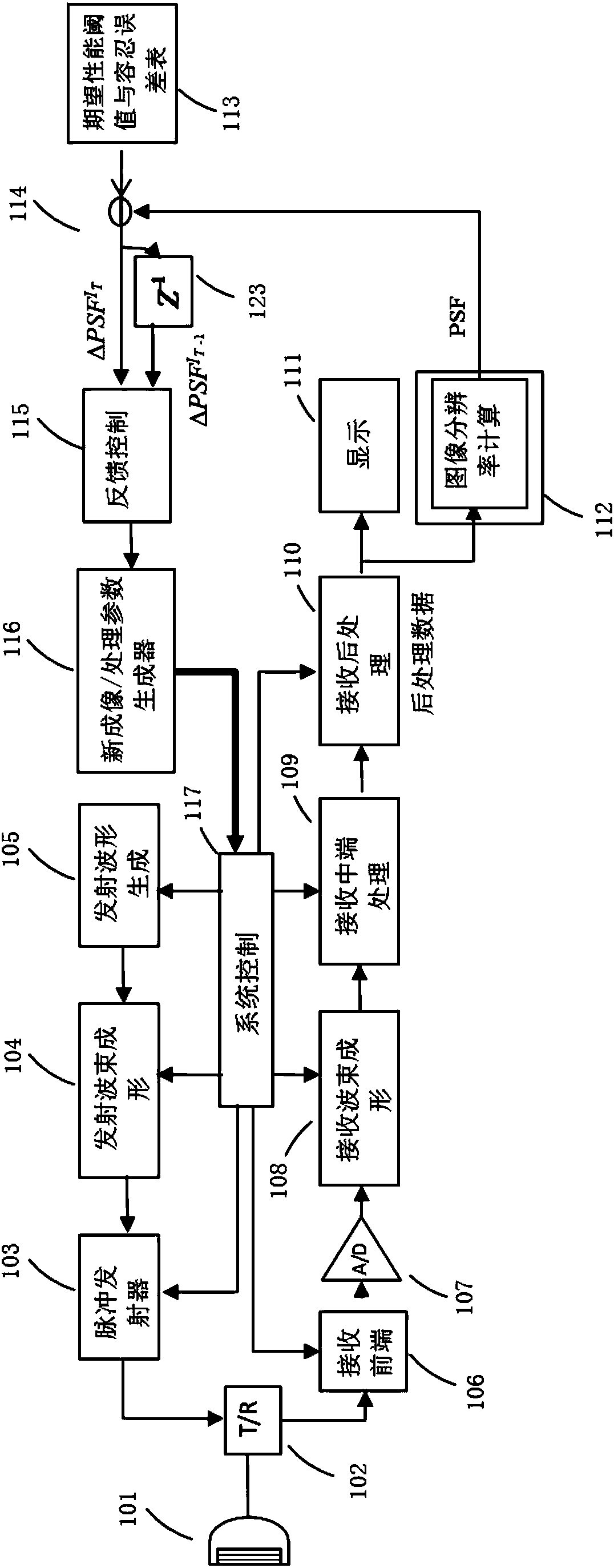
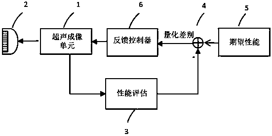
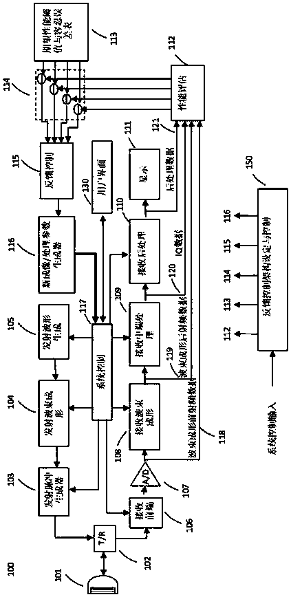
[0050] The first example is image 3 Automated B-mode imaging feedback control setup shown in schematic block diagram. When the user makes changes to B-mode imaging, such as changing the geometric size of the image, changing the clinical application of imaging (such as changing from blood vessel application to small organ application, or from abdominal application to obstetrics application, etc.), the present invention The system will detect one or more imaging performance evaluation parameters based on the first few frames of image data, such as signal-to-noise ratio, image resolution, uniformity of image resolution, image gain distribution, etc., and iteratively approximate the parameters with negative feedback. One or more imaging parameters such as transmit frequency, receive bandwidth, transmit and receive aperture, number of focus points, focus position, image gain, etc. can be adjusted in different ways. In this setting, the importance of imaging performance evaluation...

Embodiment 2

[0057] An example of another application is automated color flow imaging. When the user turns on the color blood flow imaging function or moves the blood flow attention window (ROI) in the color blood flow imaging, the system will automatically adjust one or more blood flow imaging parameters to achieve the desired performance. In this application, the system achieves the desired color flow performance index through two feedback control iterative processes. In the first feedback control iteration process, the system adjusts the quality of the color blood flow image according to the above-mentioned automatic adjustment method in the B mode to meet the requirements of the color blood flow signal-to-noise ratio and the uniformity of the color blood flow image. In the second iteration process, the system will adjust one or more blood flow imaging parameters such as pulse repetition frequency (PRF), wall filter cut-off frequency, wall filter and other parameters through feedback co...

Embodiment 3

[0060] Yet another example of the practical application of the automated ultrasound imaging system of the present invention is the adjustment of sound velocity in breast imaging. Breast tissue is very different from other parts of the human body due to its characteristic tissue irregularities. The study found that the speed of sound in breast tissue is very different from that in other tissues. Since both transmitting and receiving beamforming are based on the premise of a constant sound velocity in the tissue, that is, 1540 m / s, the change of sound velocity will seriously affect the quality of beamforming. For automated ultrasound imaging systems, this problem will be easily solved, even if the speed of sound in the breast is unknown at the start of the scan.

[0061] Figure 7 The principle block diagram of the feedback control system setting for sound velocity regulation is given. In this application, the image detail resolution at depth d, the PSF d , is used as an ind...


PUM


Abstract

The invention describes an ultrasonic imaging system which can automatically adjust an imaging parameter according to an original or processed echo which is reflected from an object, and an imaging method. Automatic adjustment is realized through a closed-loop negative-feedback control system iteration. An imaging performance evaluation parameter which is calculated according to the received original or processed ultrasonic echo is compared with a performance evaluation parameter threshold which represents an anticipated optimal imaging performance. An obtained quantification error is used forcalculating adjustment of the imaging parameter. The system finally reaches an optimal imaging effect or terminates iteration after a highest iteration number-of-times is reached.

Description

technical field [0001] The present invention relates to the technical field of ultrasonic imaging, and more specifically relates to an automatic ultrasonic imaging system and method. Background technique [0002] Today, the market for medical ultrasound technology is rapidly shifting from traditional radiology, cardiology, obstetrics and gynecology to more emerging clinical applications such as emergency, anesthesia, and musculoskeletal. The global annual sales of medical ultrasound equipment have reached More than US$6 billion, with a compound annual growth rate of about 8.5%. Compared with CT, MRI, and X-ray imaging systems, ultrasound equipment has the advantages of low price and safe use. In recent years, ultrasound equipment has rapidly entered clinics at the county, town, and village levels, and global ultrasound manufacturers continue to develop systems suitable for remote clinics or non-central areas in developing countries. Among them, the number of ultrasonic ins...

Claims


Application Information

Patent Timeline
Patent Type & Authority Applications(China)
IPC IPC(8): A61B8/00
CPCA61B8/00A61B8/5207A61B8/54
Inventor 郝晓辉
Owner 郝晓辉
Why Eureka
Try Eureka