
Machining tool for tea tank

A technology of tea cans and tooling, which is applied in the field of tea cans processing, and can solve problems such as high difficulty, easy deviation of the can body, and excessive gaps

Active Publication Date: 2018-08-28
ANHUI YILIANG TANK IDUSTRY TECH CO LTD
View PDF4 Cites 0 Cited by
  • Summary
  • Abstract
  • Description
  • Claims
  • Application Information

AI Technical Summary

Problems solved by technology

[0002] In the field of tea production, iron cans are usually used to hold tea leaves, and iron cans often need to use pressing machines during processing. The existing patent 205414193 discloses a fixing fixture for can body processing. The actual production of this device The operation is: the worker sits in front of the fixture, puts the tank body to be pressed on the fixed column, and then pushes the fixed column to the bottom of the pressing machine to process the tank body. When fixed and clamped, the degree of cooperation between the fixed column and the tank body should be high, but when the size difference between the fixed column and the tank body is small, although the tank body is not easy to shake during pressing, it will be more difficult for workers to insert the tank body If the size of the fixed column is adjusted to make it slightly smaller than the inner wall of the tank, although the worker can quickly put the tank on the fixed column, the fixed column and The gap between the tanks will be too large, and the tanks are easy to deviate, making the positioning of the tanks inaccurate, resulting in poor molding effect after pressing

Method used


Image

  • Machining tool for tea tank
  • Machining tool for tea tank
  • Machining tool for tea tank

Examples


Embodiment Construction

[0015] The preferred embodiments of the present invention will be described in detail below with reference to the accompanying drawings.

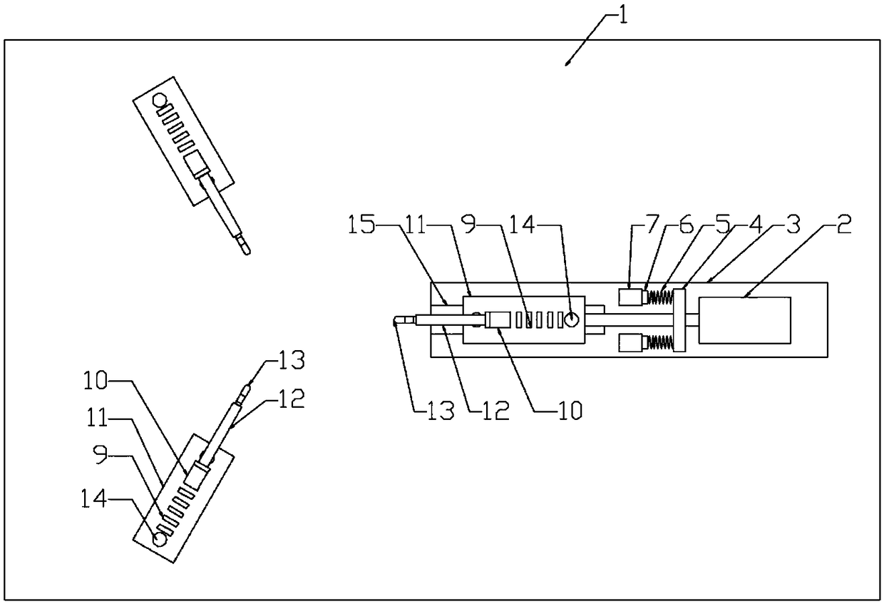
[0016] Figure 1-6 A specific embodiment of the present invention is shown: a processing tool for tea cans, including a workbench 1, on which a bottom plate 3 is provided along the length direction, and an air cylinder 2 is provided at one end of the bottom plate 3, and the bottom plate 3 The other end is provided with a sliding groove 15 which is provided with a slidingly connected sliding block 16 in which the piston rod of the cylinder 2 is connected with the sliding block 16, and the piston rod of the cylinder 2 is also sleeved with a limiting plate 4 , Both ends of the limiting plate 4 are provided with a spring 5, one end of the spring 5 is connected with a buffer block 6, the bottom plate 3 is provided with two buffer seats 7, and the buffer block 6 is located on the buffer seat 7 is inside and can be linearly moved in the length direc...


PUM


Abstract

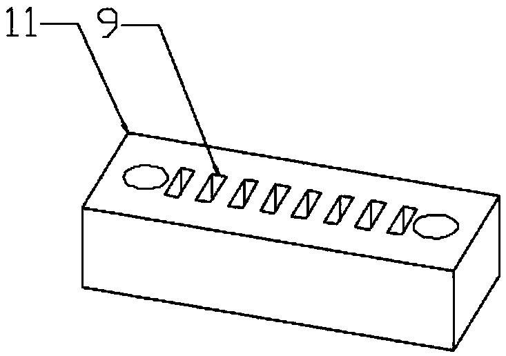
The invention discloses a machining tool for a tea tank. The machining tool for the tea tank comprises a worktable, a bottom plate is arranged on the worktable in the length direction, an air cylinderis arranged at one end of the bottom plate, a sliding groove is formed in the other end of the bottom plate, a sliding block is in sliding connection into the sliding groove, a piston rod of the aircylinder is connected with the sliding block, the piston rod of the air cylinder is sleeved with a limiting plate, first springs are arranged on the two ends of the limiting plate, one ends of the first springs are connected with buffer blocks, two buffer bases are arranged on the bottom plate, two fixed bases symmetric about the length direction of the bottom plate are arranged on the worktable,bases are arranged on the upper ends of the fixed bases and the sliding block, multiple rectangular holes are formed in the base, supports are arranged on the upper ends of the bases, casing pipes arearranged on the upper ends of the supports, second springs are arranged in the casing pipes, and one ends of the second springs are connected with ejector rods. Compared with a traditional tank bodyfixing device, the machining tool has the beneficial effects that tank body clamping force is moderate, clamping is firm, the tank body machining percent defective is reduced, meanwhile, the device can machine tank bodies of different diameters, the machining tool is wide in application range, and cost of repeated making of clamps is saved.

Description

Technical field [0001] The invention relates to the field of tea cans processing, in particular to a processing tool for tea cans. Background technique [0002] In the field of tea production, iron cans are usually used to contain tea. The processing of iron cans often requires a pressing machine. The existing patent 205414193 discloses a fixed clamp for can processing. The actual production of the device is The operation is: the worker sits in front of the fixture, puts the tank to be pressed on the fixed column, and then pushes the fixed column to the bottom of the pressing machine to process the tank. After the processing is completed, the fixed column is retracted, and the fixed column is used to perform the tank When fixing and clamping, the fit between the fixed column and the tank body should be high, but the size difference between the fixed column and the tank body is very small. Although the tank body is not easy to shake during pressing, it is more difficult for worker...

Claims


Application Information

Patent Timeline
Patent Type & Authority Applications(China)
IPC IPC(8): B21D51/26B21D43/00
CPCB21D43/003B21D51/2692
Inventor 邢永义邢婷王伟
Owner ANHUI YILIANG TANK IDUSTRY TECH CO LTD
Learn More