A straightening mechanism in a steel bar straightening machine

A technology of straightening machine and steel bar is applied in the field of construction equipment of construction engineering, which can solve the problems of inability to straighten the steel bar, cannot obtain high straightness, and it is difficult to ensure the safety and accuracy of construction projects, so as to improve the straightness, reduce bending, The effect of ensuring safety and accuracy

Active Publication Date: 2020-09-08
包松强
View PDF8 Cites 0 Cited by
  • Summary
  • Abstract
  • Description
  • Claims
  • Application Information

AI Technical Summary

Problems solved by technology

[0004] Since the orientations of the curved parts on the steel bars are not the same, the above-mentioned steel bar straightening machine can only straighten the curved parts on the plane between the pressure rollers, but cannot straighten the curved parts of other orientations on the steel bars, so that it cannot Obtain high straightness of steel bars, so it is difficult to ensure the safety accuracy of construction works

Method used


Image

  • A straightening mechanism in a steel bar straightening machine
  • A straightening mechanism in a steel bar straightening machine
  • A straightening mechanism in a steel bar straightening machine

Examples


Embodiment 1

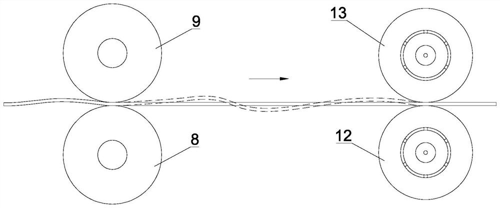
[0038] see Figure 1-3 with Figure 6-8 , the straightening mechanism in the steel bar straightening machine in the present embodiment comprises a chassis 1 and a traction unit and a straightening unit arranged on the chassis 1; wherein, the traction unit comprises two traction wheels and a driving The traction power mechanism that the traction wheel rotates; the straightening unit includes two straightening wheels that are arranged up and down oppositely and a straightening power mechanism that drives the straightening wheel to rotate. The mechanism is rotatably connected; along the conveying direction of the steel bar, the straightening wheel is located in front of the traction wheel.

[0039] In the work of steel bar straightening, the straightening power mechanism drives the linear speed of the straightening wheel to rotate greater than the linear speed of the traction power mechanism to drive the traction wheel to rotate; when the steel bar is straightened, the straighte...

Embodiment 2

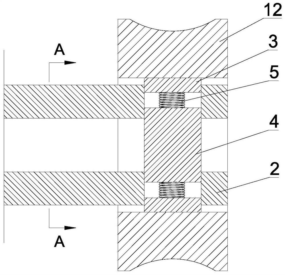
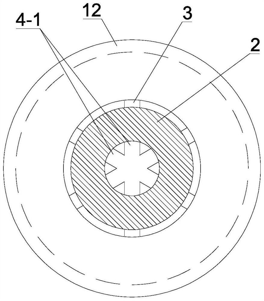
[0052] see Figure 4-5 , and the difference from Embodiment 1 is that the slidable connection structure includes a rotating shaft 2 connected to the straightening power mechanism and a first rotating member 3, a second rotating member 4, an adjusting rod 6, a compression Spring 5; wherein, the rotating shaft 2 is a hollow structure, and one end near the straightening wheel is provided with a plurality of mounting holes evenly distributed along the circumferential direction; the number of the first rotating member 3 and the second rotating member 4 Equal to the number of mounting holes, the upper end of the first rotating member 3 is on the inner hole wall of the straightening wheel, and the lower end extends into the mounting hole; the adjusting rod 6 is located in the inner hole of the rotating shaft 2, and is the same shaft, one end is the adjusting end of the truncated circular structure, and the other end is the rotating end of the cylindrical structure; the adjusting end ...


PUM


Abstract

The invention discloses a straightening mechanism in a steel bar straightening machine. The straightening mechanism comprises a machine box, a traction unit and a straightening unit, wherein the traction unit and the straightening unit are arranged on the machine box; the traction unit comprises two traction wheels which are opposite to each other up and down and a traction power mechanism for driving the traction wheels to rotate; the straightening unit comprises two straightening wheels which are opposite to each other up and down and a straightening power mechanism for driving the straightening wheels to rotate, and the straightening wheels are connected with the straightening power mechanism in a rotating mode through a slidable connecting structure; in the conveying direction of a steel bar, the straightening wheels are located in front of the traction wheels; in the steel bar straightening operation, the linear speed of the straightening power mechanism for driving the straightening wheels to rotate is larger than the linear speed of the traction power mechanism for driving the traction wheels to rotate; and after the steel bar is straightened, the straightening wheels slip,and the linear speed of the straightening wheels is equal to the linear speed of the traction wheels. According to the straightening mechanism, all bent parts with different orientations on the steelbar can be adjusted to be straight, bending on the steel bar is greatly reduced, the straightness of the steel bar is improved, and the safety accuracy of a project is ensured.

Description

technical field [0001] The invention relates to building engineering construction equipment, in particular to a straightening mechanism in a steel bar straightening machine. Background technique [0002] In reinforced concrete, steel bars are indispensable frame materials, and the processing and forming of steel bars directly affect the strength and engineering quality of reinforced concrete structures. Generally, after the steel bars are formed in the steel factory, most of the steel bars will be rolled into a circle and bundled together in order to facilitate transportation. In this way, a steel bar straightening machine must be used to straighten the steel bars during construction on the site. [0003] In the existing steel bar straightening machine, there are a plurality of pressure rollers arranged up and down. The steel bar is conveyed from the middle of the pressure roller. Straighten, then cut to the desired length of rebar. [0004] Since the orientations of the c...

Claims


Application Information

Patent Timeline
Patent Type & Authority Patents(China)
IPC IPC(8): B21F1/02
CPCB21F1/02
Inventor 冼柏恩陈誉宏
Owner 包松强
Why Eureka
Try Eureka