Cutting and marking effect optimization method for arc-shaped butt joint of laser equipment

An optimization method and technology of laser equipment, applied in laser welding equipment, welding equipment, metal processing equipment, etc., can solve problems such as control trajectory calculation errors, different motor rotation angles, and inability to align, so as to maintain consistency and accuracy, Avoid calculation errors, avoid the effects of errors

Active Publication Date: 2018-08-28
GUANGZHOU NEW CKLASER CO LTD
View PDF5 Cites 1 Cited by
  • Summary
  • Abstract
  • Description
  • Claims
  • Application Information

AI Technical Summary

Problems solved by technology

[0005] 1. The seal is not tight: the starting point and the ending point of the arc marking that should overlap cannot be completely overlapped, leaving a section that does not meet the standard
Affect the appearance, the effect is not ideal
[0006] 2. Stagger: The end point of the arc marking path deviates inward or outward compared with the starting point, which deviates from the normal track, resulting in staggering and inability to align, forming a cracked gap
[0008] 4. Out of circle and deformation: the arc marking path produces distortion, flattening, elongation, straightening and other phenomena, which affects the appearance and the effect is not ideal
[0011] If the two axes cannot coincide, the processing path will inevitably be shifted due to rotation during the laser marking process, so there will be misalignment
[0012] The low precision of the motor or defects in the manufacturing process of the motor will cause the motor to rotate at different angles, and the rotation is fast and slow under the same pulse.
[0013] 2. Calculation error of control trajectory: In order to meet the requirements of high-precision marking for current laser marking equipment, the laser point distance is generally within the range of 0.010-0.020mm
Therefore, under the current situation that the hardware part of the marking machine is basically mature, the calculation path algorithm in the control system has become a decisive factor affecting the marking quality, and the imperfect calculation path algorithm of the control system will directly lead to arc deformation and other phenomena.
[0014] 3. Errors caused by parameter setting: Improper setting of parameters such as light-on delay, light-off delay, and speed will directly affect the arc-shaped marking effect

Method used


Image

  • Cutting and marking effect optimization method for arc-shaped butt joint of laser equipment
  • Cutting and marking effect optimization method for arc-shaped butt joint of laser equipment
  • Cutting and marking effect optimization method for arc-shaped butt joint of laser equipment

Examples


Embodiment

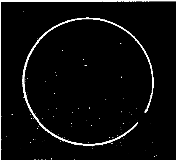
[0067] This embodiment provides a method for optimizing the cutting and marking effect of an arc-shaped interface of a laser device, which includes the following steps,

[0068] Step 1, preset, draw the required circle in advance in the control system;

[0069] In the step 1, after drawing the required circle in the control system, the control system completes the calculation of the starting position, the end position, the optimal position and the coordinates of the center point of the required circle, and according to the operator's After inputting the number of required graphics and obtaining the coordinates of the arrangement positions of multiple required graphics on the platform, go to step 2.

[0070] Step 2. Position and move the scanning head so that the working focal length of the laser corresponds to the starting point;

[0071] In the step 2, the working focal length is the distance between the laser beam generated by the laser and the surface of the material, whic...

Embodiment 2

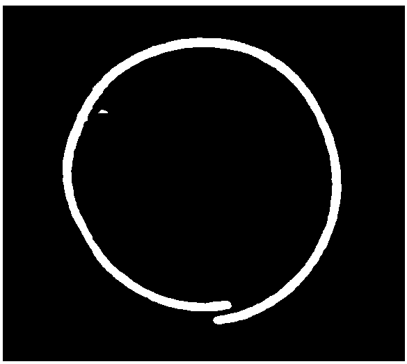
[0088] This embodiment provides a method for optimizing the cutting and marking effect of an arc-shaped interface of a laser device, which includes the following steps,

[0089] Step 1, preset, draw the required circle in advance in the control system;

[0090] In the step 1, after drawing the required graphics in the control system, the control system completes the calculation of the pre-walk position, starting position, end position, optimized position and the center point position coordinates of the required circle, and according to After the operator inputs the number of required graphics and obtains the coordinates of the arrangement positions of multiple required graphics on the platform, go to step 2.

[0091] Step 2. Position and move the scanning head so that the working focal length of the laser corresponds to the pre-moving position;

[0092] The pre-moving position is located on the extension line of the arc or the circumference of the circle on the side away from...


PUM


Abstract

The invention provides a cutting and marking effect optimization method for an arc-shaped butt joint of laser equipment. The method comprises the following steps of 1, preset; 2, positioning; 3, operation; 4, optimization; and 5, circulation. In the step 1, a required arc shape or circle is drawn in advance in a control system; in the step 2, a scanning head is moved, so that the working focal length of a laser is enabled to correspond to the starting point position; in the step 3, the laser is started, a working light source is generated, and the working light source is cut and marked according to the shape pre-drawn in the step 1; in the step 4, the arc-shaped or circular marking is started from a starting point position, and then the laser is turned off at the terminal position, so thatthe scanning head continues to go away for a certain distance under the state that the laser is close to the working light source, and an optimized position is reached; and in the step 5, after the scanning head is moved away for a certain distance, the scanning head continuously moves to the position of the starting point of the next arc or the arc according to the continuous cutting and markinginstructions sent by the control system, and the next cycle is carried out. The problems that when the laser is used for cutting or marking the arc, seals cannot be closed, and are tilted or overlapped are solved.

Description

technical field [0001] The invention relates to the technical field of marking and cutting of laser equipment, in particular to a method for optimizing the cutting and marking effect of an arc-shaped interface of a laser equipment. Background technique [0002] Laser marking machines process by focusing on extremely small light spots and extremely high energy density. In the field of marking and cutting, the advantages of laser marking machines have been fully demonstrated, replacing many traditional inkjet printing, which is environmentally friendly and beautiful. However, when the laser marking machine marks some arc-shaped workpieces such as water cups, LED lights, and metal rings, it needs to mark arc-like shapes, especially in the state of high-speed arc marking, and the dimensional accuracy of the marking parameters is less than When the thickness is 1mm, there are often unsatisfactory arc seals and dislocation of some graphics and characters. [0003] There are main...

Claims


Application Information

Patent Timeline
Patent Type & Authority Applications(China)
IPC IPC(8): B23K26/08
CPCB23K26/0876
Inventor 徐强李高
Owner GUANGZHOU NEW CKLASER CO LTD
Why Eureka
Try Eureka