Yarn inlet and guiding device for textile machine

A textile machine and wire technology, which is applied to the field of wire feed wire devices for textile machines, can solve problems such as poor wire effect and yarn breakage, and achieve the effect of improving textile effect and preventing wire breakage.

Inactive Publication Date: 2018-08-28
佛山市冠康隆纺织有限公司
View PDF0 Cites 10 Cited by
  • Summary
  • Abstract
  • Description
  • Claims
  • Application Information

AI Technical Summary

Problems solved by technology

[0002] Textile machine, also known as textile machine, loom, cotton spinning machine, etc., the ancient textile machine is a loom driven by manpower, and the textile machine is the full name of the tool that processes raw materials such as thread, silk, and hemp into silk thread and then weaves it into cloth; In the weaving process of textile yarn, in the processing technology of gauze, it is often necessary to move the yarn between the various textile machines according to a certain path to complete the weaving of gauze, and to guide and unwind the textile yarn, so as to ensure The stability of the yarn transmission process, but the thread guide in the prior art only has one yarn guide hole corresponding to a yarn. After long-term use, the yarn guide hole is easily worn out by the yarn with sharp edges, and the yarn is broken. At present, the wire effect of many yarn guide devices is not good

Method used


Image

  • Yarn inlet and guiding device for textile machine
  • Yarn inlet and guiding device for textile machine
  • Yarn inlet and guiding device for textile machine

Examples


specific Embodiment approach 1

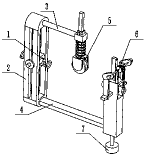
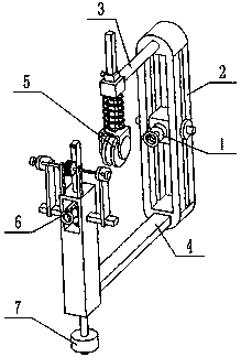
[0030] Such as Figure 1-12 As shown, an incoming wire device for a textile machine includes a wire conduit mechanism 1, a mounting frame 2, a cylindrical connecting rod 3, a rectangular connecting rod 4, a guide wheel mechanism 5, a cleaning brush assembly 6 and a dust collection pipe assembly 7, The front and rear sides of the mounting bracket 2 are provided with through rectangular slots 2-1, There is a rectangular slot on the left side and the right side of the mounting frame 2 2-2, rectangular slot 2-1 and two rectangular slots 2-2 are connected; the wire conduit mechanism 1 is connected to the rectangular slot of the mounting frame 2 2-1 and two rectangular slots 2-2 inside; the upper end of the rear side of the mounting frame 2 is fixedly connected to the cylindrical connecting rod 3, and the rear end of the cylindrical connecting rod 3 is fixedly connected to the guide wheel mechanism 5; the lower end of the rear side of the mounting frame 2 is fixedly connect...

specific Embodiment approach 2

[0031] Such as Figure 1-12 As shown, the wire conduit mechanism 1 includes a rectangular guide slider 1-1, an externally threaded wire conduit 1-2, a front wire loop 1-3, a rear wire loop 1-4, a cylindrical slide rod 1-5 and a positioning ring 1-6; the rectangular guide slider 1-1 is matched and connected in the rectangular groove 2-1; the middle of the rectangular guide slider 1-1 is provided with an internally threaded through hole, and the inner side of the internally threaded through hole is threaded to connect the externally threaded conduit 1-2; the rectangular guide slider 1-1 The left end and the right end of each are fixedly connected with a cylindrical sliding rod 1-5, and the two cylindrical sliding rods 1-5 are respectively slidingly fitted and connected in two rectangular slots On the inner side of 2-2, the outer ends of the two cylindrical slide rods 1-5 are respectively threaded to a positioning ring 1-6, and the two positioning rings 1-6 are attached to the...

specific Embodiment approach 3

[0032] Such as Figure 1-12 As shown, the guide wheel mechanism 5 includes a fixed sliding sleeve 5-1, a movable sliding sleeve 5-2, a rectangular slide bar 5-3, a guide wheel body 5-4, a wheel seat 5-5, a compression spring 5-6 and Positioning bolt 5-7; the front end of the fixed sliding sleeve 5-1 is fixedly connected to the rear end of the cylindrical connecting rod 3; the rectangular sliding rod 5-3 is slidingly fitted and connected to the fixed sliding sleeve 5-1; the rectangular sliding The upper end of the rod 5-3 is slidably fitted to connect the movable sliding sleeve 5-2, and the movable sliding sleeve 5-2 is threaded to connect the positioning bolt 5-7, and the positioning bolt 5-7 is against the rectangular sliding rod 5-3; The lower end of the slide bar 5-3 is connected to the wheel seat 5-5 by screws; the guide wheel body 5-4 is connected to the inner lower end of the wheel seat 5-5 through rotation of the rotating shaft; the upper sleeve of the rectangular slide...


PUM


Abstract

The invention relates to the field of textile processing equipment, in particular to a yarn inlet and guiding device for a textile machine. The yarn inlet and guiding device for the textile machine comprises a yarn guiding pipe mechanism, a mounting frame, a cylinder connection rod, a rectangular connection rod, a yarn guiding wheel mechanism, a dust removing brush assembly and a dust collecting pipe assembly; a through rectangular groove I is formed in the front and back side faces of the mounting frame; the left side face and the right side face of the mounting frame are each provided with one rectangular groove II; the rectangular groove I and the two rectangular grooves II communicate with each other; the yarn guiding pipe mechanism is connected to the inner sides of the rectangular groove I and the two rectangular grooves II of the mounting frame; the upper end of the rear side face of the mounting frame is fixedly connected with the cylinder connection rod; and the rear end of the cylinder connection rod is fixedly connected with the yarn guiding wheel mechanism. The yarn guiding pipe mechanism inside the yarn inlet and guiding device is used for guiding yarns and properly adjusting the guiding height and direction of the yarns, and requirements of different textile machines are met conveniently.

Description

technical field [0001] The invention relates to the field of textile processing equipment, in particular to an incoming wire device for a textile machine. Background technique [0002] Textile machine, also known as textile machine, loom, cotton spinning machine, etc., the ancient textile machine is a loom driven by manpower, and the textile machine is the full name of the tool that processes raw materials such as thread, silk, and hemp into silk thread and then weaves it into cloth; In the weaving process of textile yarn, in the processing technology of gauze, it is often necessary to move the yarn between the various textile machines according to a certain path to complete the weaving of gauze, and to guide and unwind the textile yarn, so as to ensure The stability of the yarn transmission process, but the thread guide in the prior art only has one yarn guide hole corresponding to a yarn. After long-term use, the yarn guide hole is easily worn out by the yarn with sharp ed...

Claims


Application Information

Patent Timeline
Patent Type & Authority Applications(China)
IPC IPC(8): B65H57/14D02J7/00
CPCB65H57/14D02J7/00
Inventor 冼瑞辉
Owner 佛山市冠康隆纺织有限公司
Why Eureka
Try Eureka