Mooring rope lock device

A lock and cable technology, applied in the field of lock devices, can solve the problems that the padlock is not so obvious, the operation is complicated, and the cost is high, so as to avoid industrial safety accidents, the effect of locking is remarkable, and the effect of avoiding economic losses is achieved.

Pending Publication Date: 2018-08-28
SUZHOU DUKE SECURITY TECH
View PDF5 Cites 3 Cited by
  • Summary
  • Abstract
  • Description
  • Claims
  • Application Information

AI Technical Summary

Problems solved by technology

[0002] At present, there are many kinds of cable locks on the market, which can lock switches / valves, especially in many factories such as oil refineries and chemical plants, which play a certain role in safety protection. Among the locks on the market now, padlocks are It is the most widely used, but in some special occasions, the effect of the padlock is not so significant. For example, when locking some objects with a large cross-sectional area or a large span, the padlock cannot lock the object. Apparently padlocks cannot meet the needs, and most of the current cable locks need to be locked with a padlock, which is costly, complicated to operate, and difficult to manage and messy
[0003] To sum up, the problems in the prior art are: the existing locks cannot lock the object, and the lock is realized by locking the padlock twice, and there is no direct control of the opening / closing function of the cable through the built-in lock cylinder
At present, most cable locks need to be locked with a padlock, which is costly, complicated to operate, and difficult to manage.

Method used


Image

  • Mooring rope lock device
  • Mooring rope lock device
  • Mooring rope lock device

Examples


Embodiment Construction

[0029] In order to further understand the content, features and effects of the present invention, the following examples are given, and detailed descriptions are given below with reference to the accompanying drawings.

[0030] The structure of the present invention will be described in detail below in conjunction with the accompanying drawings.

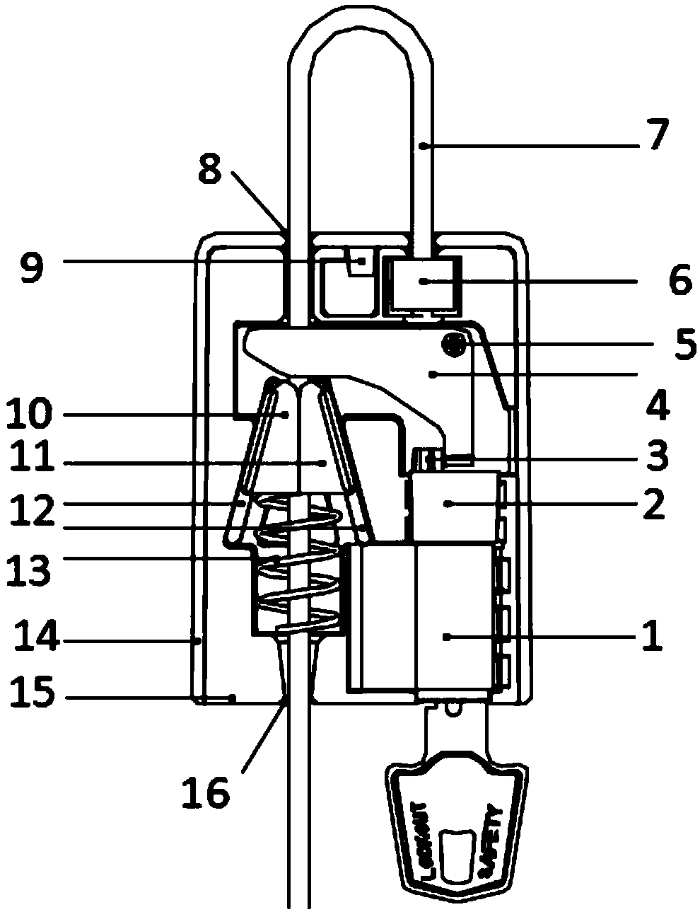
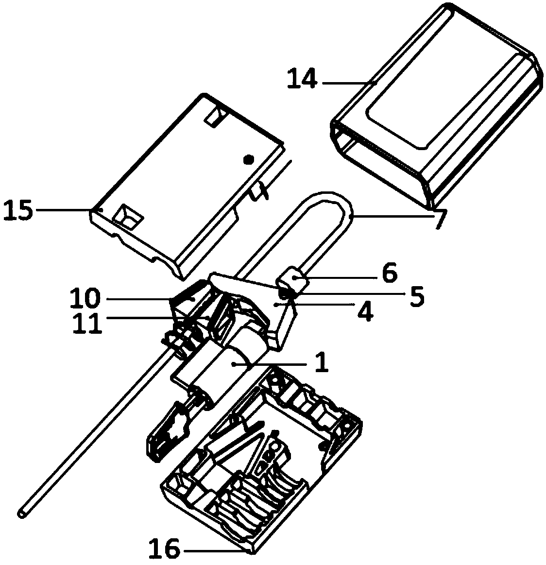
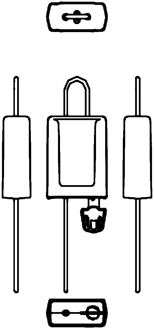
[0031] Such as Figure 1 to Figure 5 As shown, the cable lock device provided by the embodiment of the present invention includes: a lock cylinder 1, a circular transmission member 2, a circular transmission member cam 3, a shift block 4, a shift block shaft 5, a metal fixing seat 6, a steel cable 7, and a steel cable inlet 8. Shell hook 9, first barb tooth extruding block 10, second barb tooth extruding block 11, guide groove 12, spring 13, shell 14, upper pressing plate 15, steel cable outlet 16.

[0032] A lock cylinder 1 is arranged inside the casing 14, and the circular transmission part 2 is clamped on the top of the lock cyli...


PUM


Abstract

The invention belongs to the technical field of lock devices, and discloses a mooring rope lock device. A lock cylinder is arranged in a shell, an oval transmission part is clamped above the lock cylinder, an oval transmission part cam is welded to the left side of the upper portion of the oval transmission part, a moving block is arranged in the shell through a moving block shaft, a metal fixed base is arranged above the moving block, the right end of a steel cable is clamped to the metal fixed base, the left end of the steel cable is inserted from a steel cable inlet, and extends out from asteel cable outlet, a shell clamping hook is welded to the breaking position of the upper portion of the interior of the shell, guide grooves are sleeved with rear ends of a first inverted tooth extrusion block and a second inverted tooth extrusion block, and the lower portion of a spring is placed on an upper pressing plate. A mooring rope penetrates many targets to be locked, for example, the mooring rope penetrates a disc valve to be fixed to a pipeline, the locking effect is obvious, the rope is not prone to loosening, the protection effect on safety production and maintaining is achieved,many industrial safety accidents can be avoided, and meanwhile, unnecessary economic losses are avoided, and production efficiency is improved.

Description

technical field [0001] The invention belongs to the technical field of lock devices, in particular to a cable lock device. Background technique [0002] At present, there are many kinds of cable locks on the market, which can lock switches / valves, especially in many factories such as oil refineries and chemical plants, which play a certain role in safety protection. Among the locks on the market now, padlocks are It is the most widely used, but in some special occasions, the effect of the padlock is not so significant. For example, when locking some objects with a large cross-sectional area or a large span, the padlock cannot lock the object. Apparently padlocks cannot meet the demand, and most of the cable locks at present need to be locked with padlocks, which are costly, complicated to operate, and difficult to manage and messy. [0003] To sum up, the problem in the prior art is that the existing locks cannot lock the object, and the lock is realized by locking the padl...

Claims


Application Information

Patent Timeline
Patent Type & Authority Applications(China)
IPC IPC(8): E05B67/00
CPCE05B67/003
Inventor 廖国刚
Owner SUZHOU DUKE SECURITY TECH
Why Eureka
Try Eureka