
Gas mixer

A mixer and gas technology, which is applied to burners, gas fuel burners, combustion methods, etc., can solve the problems of limited mixing efficiency, uniform mixing of air flow and gas flow, and short length of gas mixing pipe, so as to increase combustion. The effect of efficiency

Active Publication Date: 2018-08-28
GRAND MATE
View PDF6 Cites 0 Cited by
  • Summary
  • Abstract
  • Description
  • Claims
  • Application Information

AI Technical Summary

Problems solved by technology

Although the combustion efficiency of the fully premixed gas combustion device is higher than that of the atmospheric gas combustion device, the mixing effect of the gas mixing tube is difficult to control, and the length of the gas mixing tube is usually not long, and the air flow and the gas flow cannot be mixed in the gas. Uniform mixing in the limited travel distance in the tube, the mixing efficiency is limited, resulting in the combustion efficiency of the combustion device cannot be further improved

Method used


Image

  • Gas mixer
  • Gas mixer
  • Gas mixer

Examples


Embodiment Construction

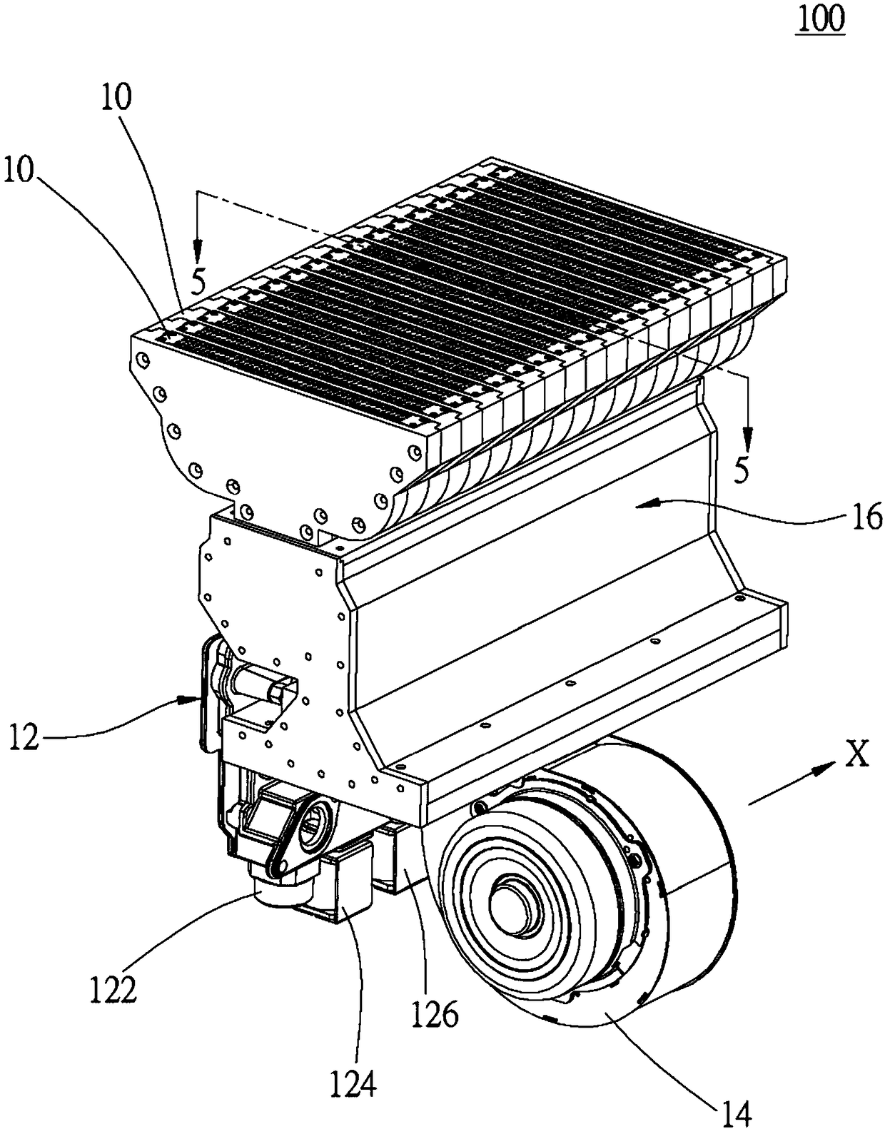
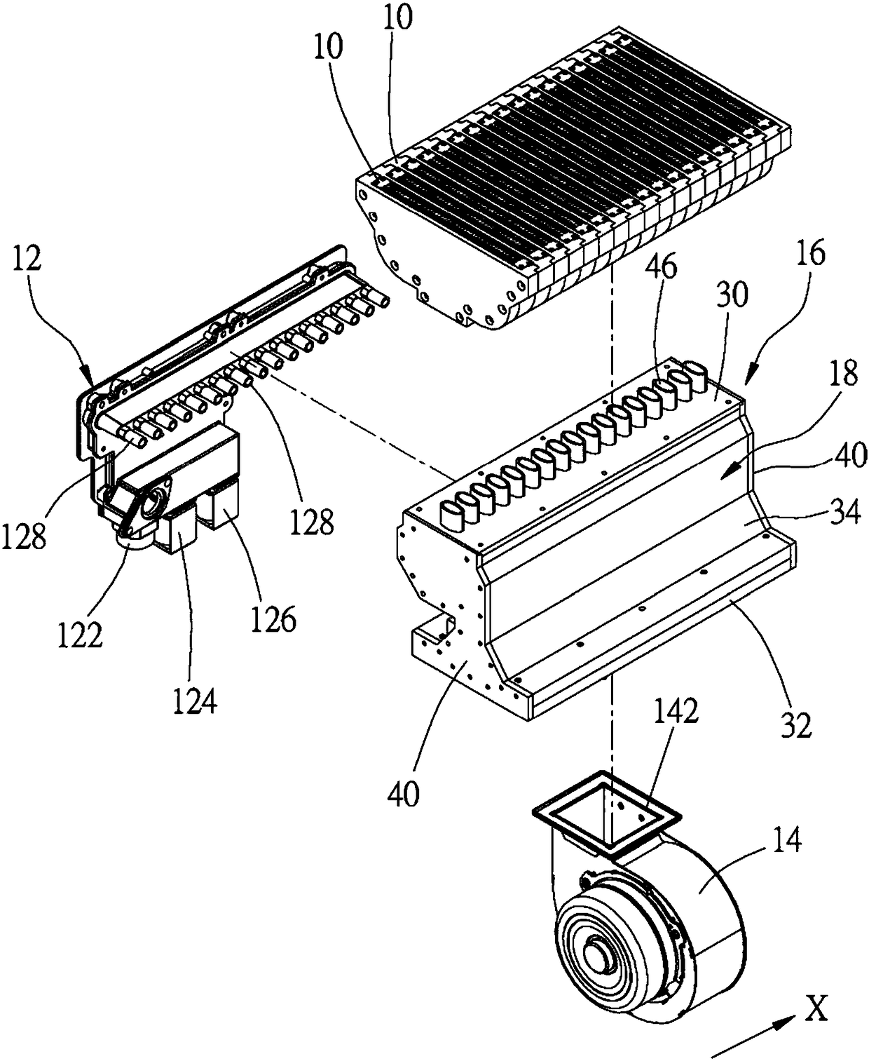
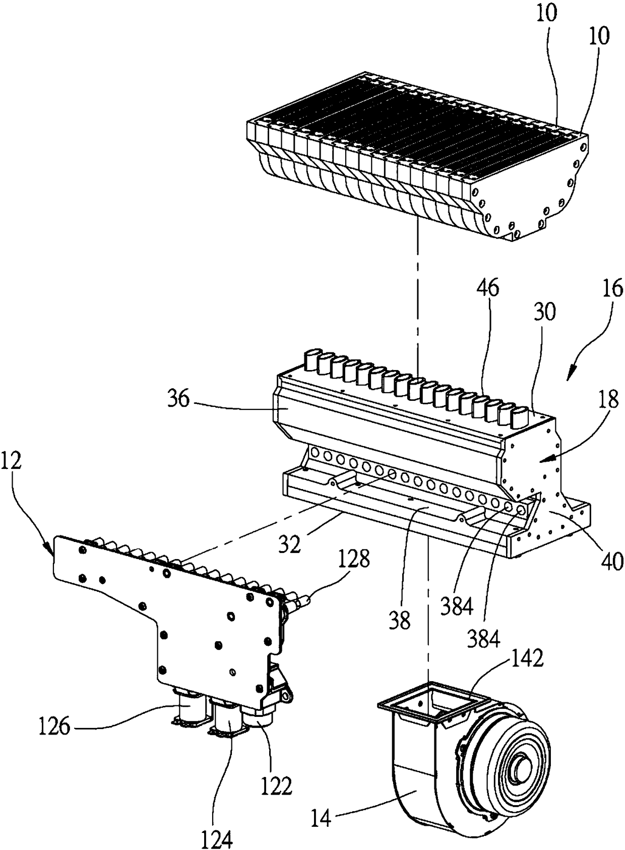
[0049] In order to illustrate the present invention more clearly, a preferred embodiment is now given and described in detail with accompanying drawings as follows. Please refer to Figure 1 to Figure 10 Shown is a gas combustion device 100 with a gas mixer according to the first preferred embodiment of the present invention. The gas combustion device 100 is applied to a water heater as an example, and includes at least one burner 10, a gas intake assembly 12, A blower 14 and the gas mixer 16 of this embodiment.

[0050] The at least one burner 10 is multiple and arranged along a predetermined axis X, and each burner 10 is used to burn gas to generate a flame. The gas intake assembly 12 includes a connection pipe, a solenoid valve 124, a proportional valve 126 and at least one nozzle 128, wherein the connection pipe 122 is connected to a gas source (not shown); the solenoid valve 124 is used to control the opening and closing Or block the gas path; the proportional valve 126...


PUM


Abstract

The invention relates to a gas mixer. The gas mixer comprises a main body and a flow distribution member. The main body is provided with an air inlet part and an air mixing part. The air inlet part isprovided with an air inlet, an air chamber, at least one gas inlet and an air vent which are communicated with one another. The air chamber is provided with two opposite wall surfaces, the wall surfaces are inclined, and the distance between the wall surfaces is gradually reduced from the air inlet to the air vent. The gas inlet is positioned in one of the wall surfaces. The gas mixing part is provided with a mixing chamber which is communicated with the air vent and burners. The flow distribution member is arranged in the air chamber and is positioned between the gas inlets and the air inlet, and the flow distribution member is provided with at least one through hole facing one of the wall surfaces. Therefore, the gas flow and the air flow are fully premixed and then output to the burners, so that the air-fuel ratio can be accurately controlled, and the combustion efficiency of the burners can be improved.

Description

technical field [0001] The present invention relates to a gas burning device; in particular, it refers to a gas mixer for mixing gas and air. Background technique [0002] The traditional atmospheric gas combustion device is to install a nozzle at the gas inlet of the burner, and use the low pressure formed around the nozzle when the gas is output from the nozzle to introduce primary air into the burner to mix with the gas, and then output the gas through the fire outlet of the burner. After the gas is ignited, a flame is formed, and when the flame burns, secondary air is introduced from around the flame to burn. Another type of gas combustion device is the full premix type, which uses a blower to introduce air into the burner to mix with the gas, and outputs the mixed gas and air from the fire outlet of the burner. [0003] The fully premixed gas combustion device uses the gas mixing tube as the gas and air vessel to mix. The gas mixing tube uses the principle of the Ventu...

Claims


Application Information

Patent Timeline
IPC IPC(8): F23D14/62
CPCF23D14/62
Inventor 黄重景黄锦颖黄信铭黄信雄叶严仁陈维隆林冠州罗堂元
Owner GRAND MATE
Learn More