Cooling regulation system and method for cooling regulation

A technology for adjusting the system, the coolant, the refrigerant flow in the evaporator, the automatic cooling adjustment system, the field of automatic cooling adjustment

Active Publication Date: 2018-08-28
HITACHI ENERGY SWITZERLAND AG
View PDF4 Cites 3 Cited by
  • Summary
  • Abstract
  • Description
  • Claims
  • Application Information

AI Technical Summary

Problems solved by technology

However, this solution requires an auxiliary power supply for the valves and temperature sensors, which can be problematic to impleme

Method used


Image

  • Cooling regulation system and method for cooling regulation
  • Cooling regulation system and method for cooling regulation
  • Cooling regulation system and method for cooling regulation

Examples


Embodiment Construction

[0021] Reference will now be made in detail to various embodiments, one or more examples of which are illustrated in the various figures. Each example is provided by way of explanation, and not intended to be limiting. For example, features illustrated or described as part of one embodiment can be used on or in conjunction with any other embodiment to yield a further embodiment. It is intended that the present disclosure includes such modifications and variations.

[0022] In the following description of the figures, the same reference numerals designate the same or similar components. In general, only the differences with respect to individual embodiments are described. Unless otherwise specified, descriptions of components or aspects in one embodiment are also applicable to corresponding components or aspects in another embodiment.

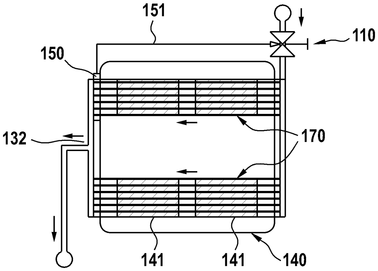
[0023] figure 1 A schematic diagram of a cooling modulation system 100 according to embodiments described herein is shown. The cooling reg...


PUM


Abstract

A cooling regulation system (100) is described which includes: a valve (110) having an control device (120) configured for controlling an opening of an orifice (111) provided between a valve inlet (112) and a valve outlet (113) such that a flow of a coolant from the valve inlet to the valve outlet can be regulated; an evaporator (130) with a contact surface that is adapted to be thermally connected to a heat source (140, 141) such that a thermal load from the heat source is dissipated by the evaporator in an operating state of the cooling regulation system; and a regulation device (150) configured for regulating a position of the control device in order to regulate the flow of the coolant, wherein the regulation device is in thermal contact with the evaporator at a position at which a vapor quality [chi] of the coolant is [chi]<=[chi]cr, wherein [chi]cr is the critical vapor quality.

Description

technical field [0001] Embodiments of the present disclosure relate to cooling tuning systems and methods for cooling tuning. In particular, embodiments of the present disclosure relate to automatic cooling adjustment systems and methods for automatic cooling adjustments. More particularly, embodiments of the present disclosure relate to systems and methods suitable for automatically adjusting refrigerant flow in an evaporator of a cooling trim system. Background technique [0002] In contemporary high voltage direct current (HVDC) converters, insulated gate bipolar transistors (IGBTs) are typically cooled with forced water flow. However, as technology trends toward more compact designs, conventional thermal management may become insufficient. The main reason is that the overall heating power density increases because the heat-generating components (IGBTs) are more closely packed together. In order to overcome the thermal management problems that arise, cooling systems fo...

Claims


Application Information

Patent Timeline
IPC IPC(8): F25B41/04F25B49/00H01L23/473
CPCF25B49/00H01L23/473F25B41/335F28F27/02F28D15/0266F28D15/06F25B49/02F25B2341/0682F25B2600/2513H05K7/20936
Inventor O.索洛古本科L.考夫曼恩
Owner HITACHI ENERGY SWITZERLAND AG
Why Eureka
Try Eureka