
Roundness and cylindricity measurement device

A measuring device and cylindricity technology, which is applied in the field of measuring devices for cylindrical products, can solve the problems of reduced sensitivity, stylus aging, time-consuming and labor-intensive problems, and achieve the effects of reducing winding and tearing, preventing falling damage, and widening the application range

Pending Publication Date: 2018-08-28
昆山世纪三友测量技术有限公司
View PDF10 Cites 10 Cited by
  • Summary
  • Abstract
  • Description
  • Claims
  • Application Information

AI Technical Summary

Problems solved by technology

If the manual detection method is adopted one by one, it will not only take time and effort, increase the labor cost, but also affect the production efficiency; using the measuring equipment of roundness and cylindricity, the object to be measured is loaded on the rotary table, and then the rotary table rotates, At the same time, the contact stylus is used to detect the surface position of the measured rotating body, etc., so as to collect the surface position data of the product to be tested, and then measure and calculate the roundness and cylindricity. The use of the stylus needs to contact the workpiece and interact with the surface of the workpiece. Sometimes it will cause damage to the surface of the workpiece. At the same time, long-term work will also cause the aging of the stylus and reduce the sensitivity. It is necessary to replace the stylus
[0003] In recent years, non-contact roundness and cylindricity measuring devices have gradually entered the market. For example, eddy current displacement sensors, laser sensors, etc. are used as detection components, which can well protect the surface of the product to be tested, but the product to be tested is not a regular cylinder , and there is a raised part on the cylindrical surface, for the upper or lower surface of the raised part, the non-contact measuring device cannot perform effective roundness detection

Method used


Image

  • Roundness and cylindricity measurement device
  • Roundness and cylindricity measurement device
  • Roundness and cylindricity measurement device

Examples


Embodiment Construction

[0024] The following are specific embodiments of the present invention. In conjunction with the accompanying drawings, the technical solution of the present invention is further described, but the present invention is not limited to these embodiments.

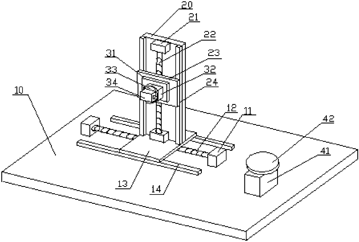
[0025] Such as figure 1 As shown, a cylindricity measuring instrument includes a base 10, a measuring system and a rotating system arranged on the base, and the rotating system is located on one side of the measuring system;

[0026] The measuring system includes a horizontal moving part arranged on the base, a vertical moving part connected to the horizontal moving part, and a detection part arranged on the vertical moving part;

[0027] The horizontal movement part comprises the first servo motor 11 arranged on the machine base, the horizontal screw mandrel 12 connected with the first servo motor 11, the horizontal movement block 13 arranged on the horizontal screw mandrel 12, and the horizontal movement block for supporting ...


PUM


Abstract

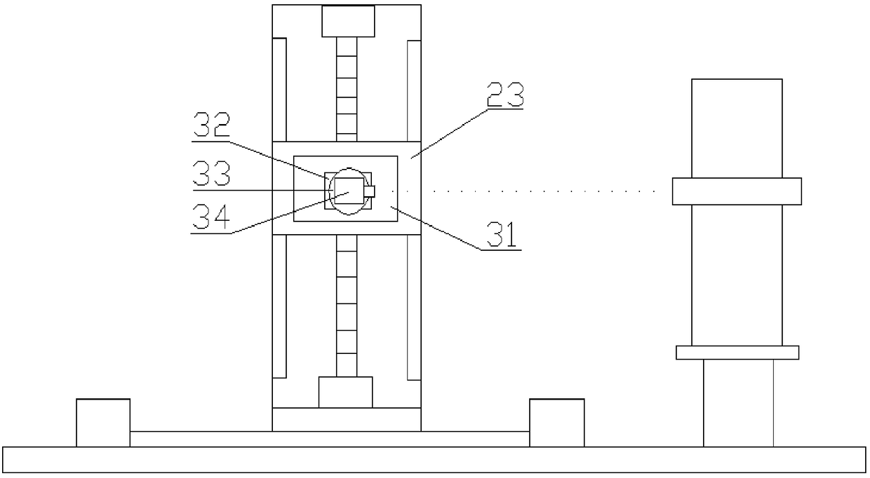
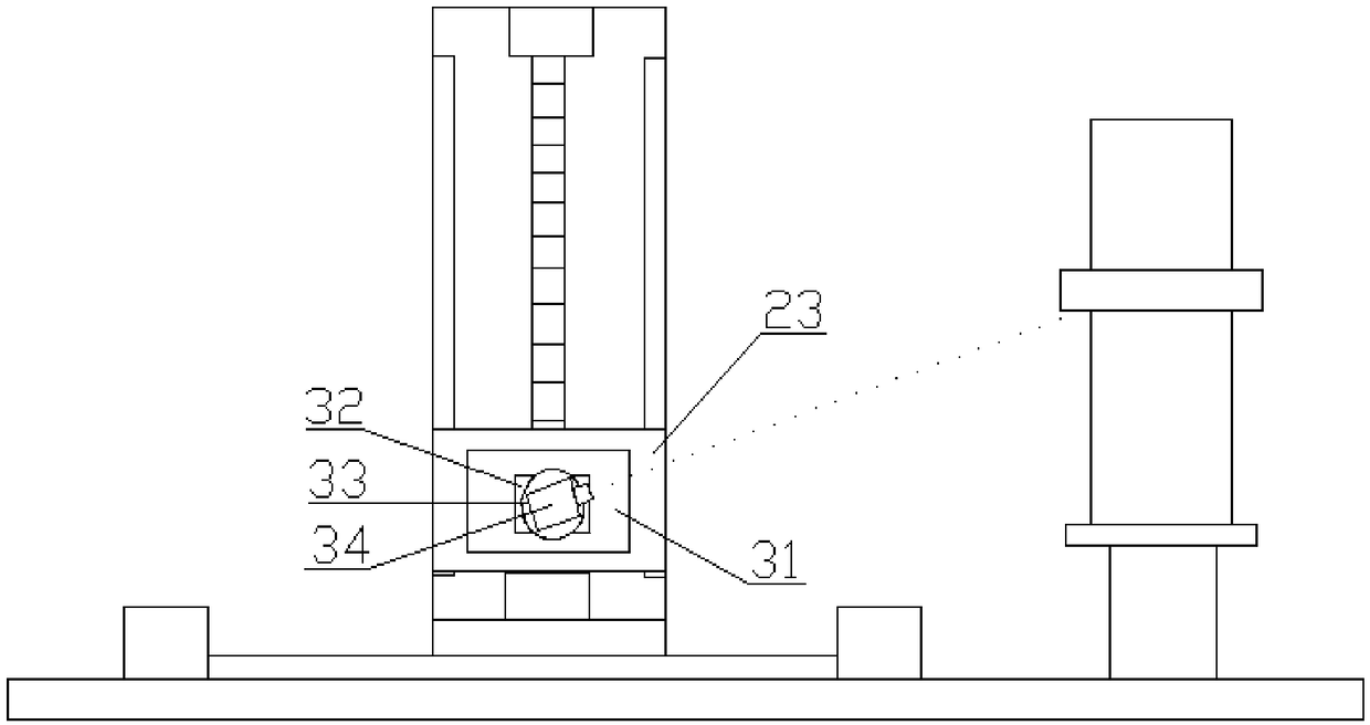
The invention discloses a roundness and cylindricity measurement device. The device comprises a base, a measurement system arranged on the base, and a rotating system; the measurement system comprisesa horizontal movement portion, a vertical movement portion connected with the horizontal movement portion, and a detecting portion arranged on the vertical movement portion; the detecting portion includes an angle adjusting device and a laser detector; the horizontal movement portion controls the laser detector to perform fore and aft movement in a horizontal direction; the vertical movement portion controls the laser detector to move up and down; and the angle adjusting device is provided with a third motor and a first turntable and adjust an angle between the laser detector and the horizontal direction, so that the deviation detection of the circular shape of the annular protruding portion of a cylindrical product to be measured can be realized. The device of the invention has a wider application range.

Description

technical field [0001] The invention relates to a measuring device for cylindrical products, in particular to a non-contact measuring device for roundness and cylindricity. Background technique [0002] Cylindrical products such as bearings often need to collect relevant data on the deviation between the product to be tested and the circular shape, such as roundness, concentricity, coaxiality, etc., to check whether the product meets the requirements. If the manual detection method is adopted one by one, it will not only take time and effort, increase the labor cost, but also affect the production efficiency; using the measuring equipment of roundness and cylindricity, the object to be measured is loaded on the rotary table, and then the rotary table rotates, At the same time, the contact stylus is used to detect the surface position of the measured rotating body, etc., so as to collect the surface position data of the product to be tested, and then measure and calculate the...

Claims


Application Information

Patent Timeline
IPC IPC(8): G01B11/24
CPCG01B11/24G01B11/2408
Inventor 谢锡良张春玲
Owner 昆山世纪三友测量技术有限公司
Learn More