An installation method for a tile-oriented distributed computing device

A technology of distributed calculation and installation method, applied in the direction of calculation, design optimization/simulation, instruments, etc., can solve the problems of increasing decoration cost, destroying the beauty of laying, and easy damage of floor tiles.

Active Publication Date: 2019-06-07
佛山市顺德区海瑞斯装饰工程有限公司
View PDF7 Cites 0 Cited by
  • Summary
  • Abstract
  • Description
  • Claims
  • Application Information

AI Technical Summary

Problems solved by technology

[0007] Yet no matter what kind of laying method, the current floor tiles are all directly laid by the workers, and the workers are based on one end of the wall, laying in turn, until the size is not enough or there is a slight error, the floor tiles are cut to ensure that the laying work is carried out, and due to The tools of laying workers are limited, and the cutting of floor tiles is not only easy to damage the floor tiles, but also increases the cost of decoration and destroys the beauty of laying

Method used


Image

  • An installation method for a tile-oriented distributed computing device
  • An installation method for a tile-oriented distributed computing device
  • An installation method for a tile-oriented distributed computing device

Examples


Embodiment 1

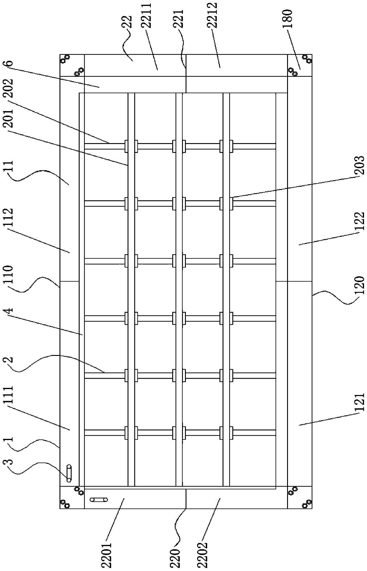
[0045] combine Figure 1-Figure 4 and Figure 7 As shown, a tile distribution calculation device disclosed in this embodiment includes a tile distribution simulation frame 1 and a tile distribution simulation rod group 2; the tile distribution simulation frame 1 is provided with several sets of tile distribution simulation rod groups vertically staggered 2;

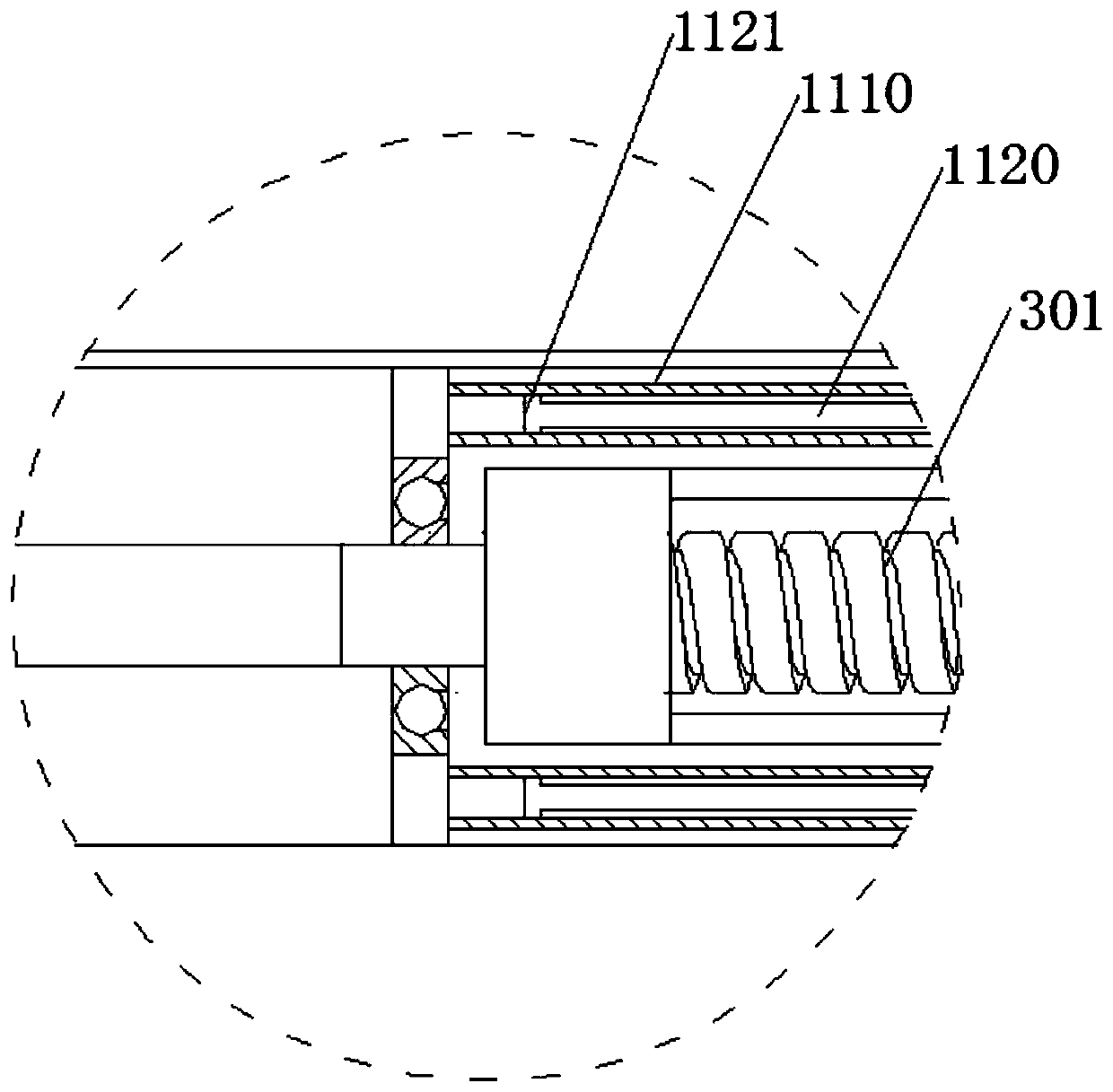
[0046] The tile distribution simulation frame 1 includes a simulation beam group 11 and a simulation vertical beam group 22; the simulation beam group 11 includes an active extension simulation beam 110 and a follow-up extension simulation beam 120, and the active extension simulation beam 110 includes a first beam 111 and the second crossbeam 112, the first crossbeam 111 and the second crossbeam 112 are arranged oppositely, the left end surface of the first crossbeam 111 is processed with four extension grooves 1110, the second crossbeam 112 and the Four sets of extension connecting rods 1120 are arranged on the opposi...

Embodiment 2

[0050] Such as Figure 5-6 As shown, on the basis of the first embodiment, both ends of the active extension simulation beam 110 and the follow-up extension simulation beam 120 are provided with a set of first extension connecting flaps 150, and the first extension connecting flaps 150 are A right-angled triangle wing plate, and a group of connection positioning columns 140 are arranged on the hypotenuse of the first extended connecting wing plate 150, and a group of second The extension connecting wing 160, the second extending connecting wing 160 is also a right-angled triangle wing, and corresponds to the size of the first extending connecting wing 150, and the hypotenuse of the second extending connecting wing 160 is processed with The connection positioning hole corresponding to the connection positioning column 140, the first extended connecting wing 150 and the second extended connecting wing 160 are detachably connected through the matching relationship between the con...

Embodiment 3

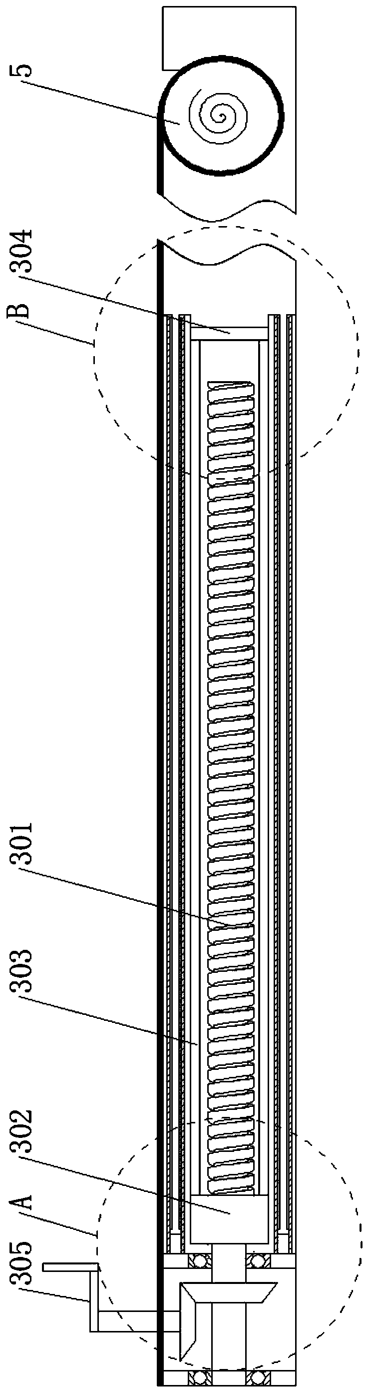
[0052] Such as Figure 2-4 On the basis of the second embodiment shown, the extension driving device 3 in this embodiment includes an extension screw 301, and a group of screw nuts 302 are arranged on the extension screw 301. Two sets of extension drive rods 303, the other ends of the two sets of extension drive rods 303 are fixedly connected with a set of extension push plates 304, the other end of the extension screw 301 is provided with a set of driven helical gears, the driven The helical gear meshes with a group of driving helical gears, the driving helical gear is fixedly connected with a group of driving handles 305, and the extended push plate 304 arranged inside the first crossbeam 111 is fixedly connected with the end of the second crossbeam 112; The extended push plate 304 inside the first vertical beam 2201 is fixedly connected with the end of the second vertical beam 2202 .


PUM


Abstract

The invention relates to the technical field of floor tile laying simulation equipment, in particular to an installing structure for a tile distributed computing device. The installing structure comprises a tile distributed simulation frame and a tile distributed simulation rod set; a plurality of sets of perpendicularly-intersecting tile distributed simulation rod sets are arranged inside the tile distributed simulation frame; by simulating the floor laying condition in a floor tile sale place in advance, which size is left or overflow is directly obtained, floor tiles are cut by a special tool on site or floor tiles of other sizes are directly selected and purchases so as to ensure the laying attractiveness.

Description

technical field [0001] The invention relates to the technical field of floor tile laying simulation equipment, in particular to an installation method for a tile distribution computing device. Background technique [0002] Floor tiles, also known as floor tiles, are a kind of ground decoration material. Fired with clay; various specifications; firm in quality, small in bulk density, pressure-resistant, wear-resistant, and moisture-proof; The types of bricks include whole body bricks, glazed tiles, whole body polished tiles, seepage tiles, seepage polished tiles, etc. These floor tiles are not all non-slip, especially if there are old people and children at home, you must do a non-slip test before purchasing. so as not to cause problems. Common floor tiles include: fully polished glazed tiles, vitrified tiles, polished tiles, matt tiles, glazed tiles, printed tiles, non-slip tiles, special acid-proof floor tiles; [0003] There are two ways to lay floor tiles, one is dry l...

Claims


Application Information

Patent Timeline
Patent Type & Authority Patents(China)
IPC IPC(8): G06F17/50
CPCG06F30/13G06F30/20
Inventor 闫丽华
Owner 佛山市顺德区海瑞斯装饰工程有限公司
Why Eureka
Try Eureka