Electric power distribution cabinet convenient to move

A technology of power distribution cabinets and movable shafts, which is applied to substation/power distribution device shells, electrical components, substation/switch layout details, etc. It can solve problems such as loose internal parts, low reliability, and wear on the outer surface of the box, and achieve Prevent loosening, ensure normal use, and avoid human dragging

Inactive Publication Date: 2018-08-28
王在江
View PDF0 Cites 0 Cited by
  • Summary
  • Abstract
  • Description
  • Claims
  • Application Information

AI Technical Summary

Problems solved by technology

[0003] The purpose of the present invention is to provide a power distribution cabinet that is easy to move, which has the advantage of being easy to move, and solves the problem that the existing power distribution cabinet itself does not have mobility and often needs to be moved by manual handling or dragging. Dragging back and forth can easily cause internal parts to loosen, and cause serious wear and tear on the outer surface of the box, resulting in the failure of the power distribution cabinet to work normally and low reliability

Method used


Image

  • Electric power distribution cabinet convenient to move
  • Electric power distribution cabinet convenient to move
  • Electric power distribution cabinet convenient to move

Examples


Embodiment Construction

[0015] The following will clearly and completely describe the technical solutions in the embodiments of the present invention with reference to the accompanying drawings in the embodiments of the present invention. Obviously, the described embodiments are only some, not all, embodiments of the present invention. Based on the embodiments of the present invention, all other embodiments obtained by persons of ordinary skill in the art without making creative efforts belong to the protection scope of the present invention.

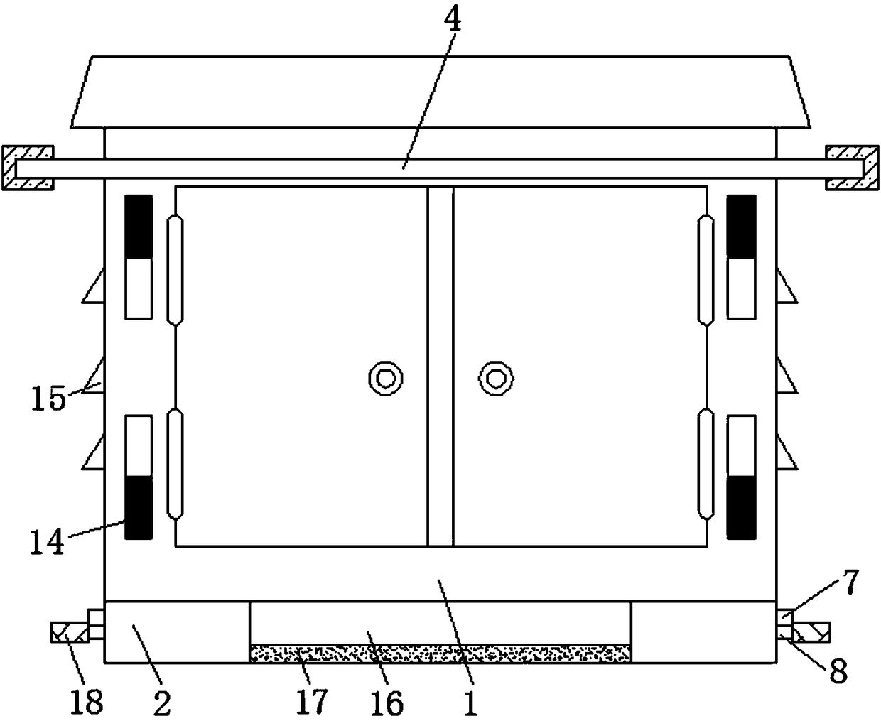
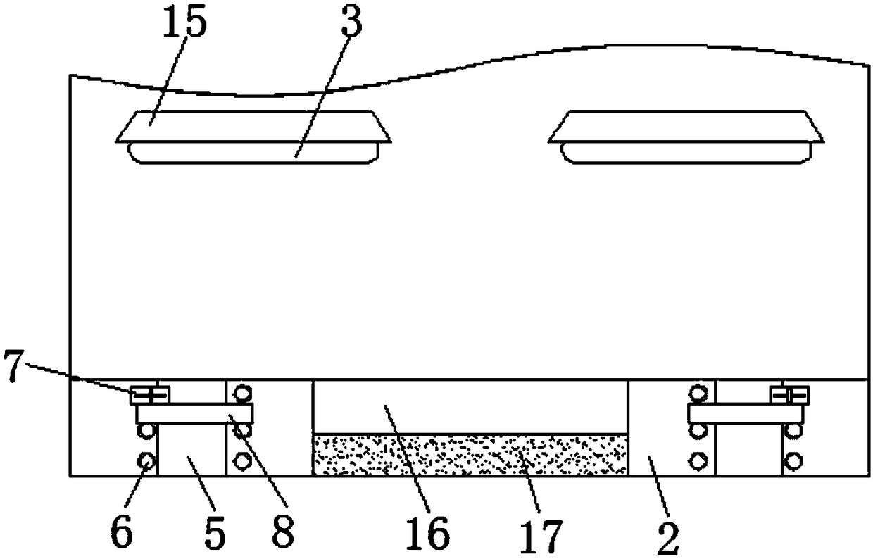
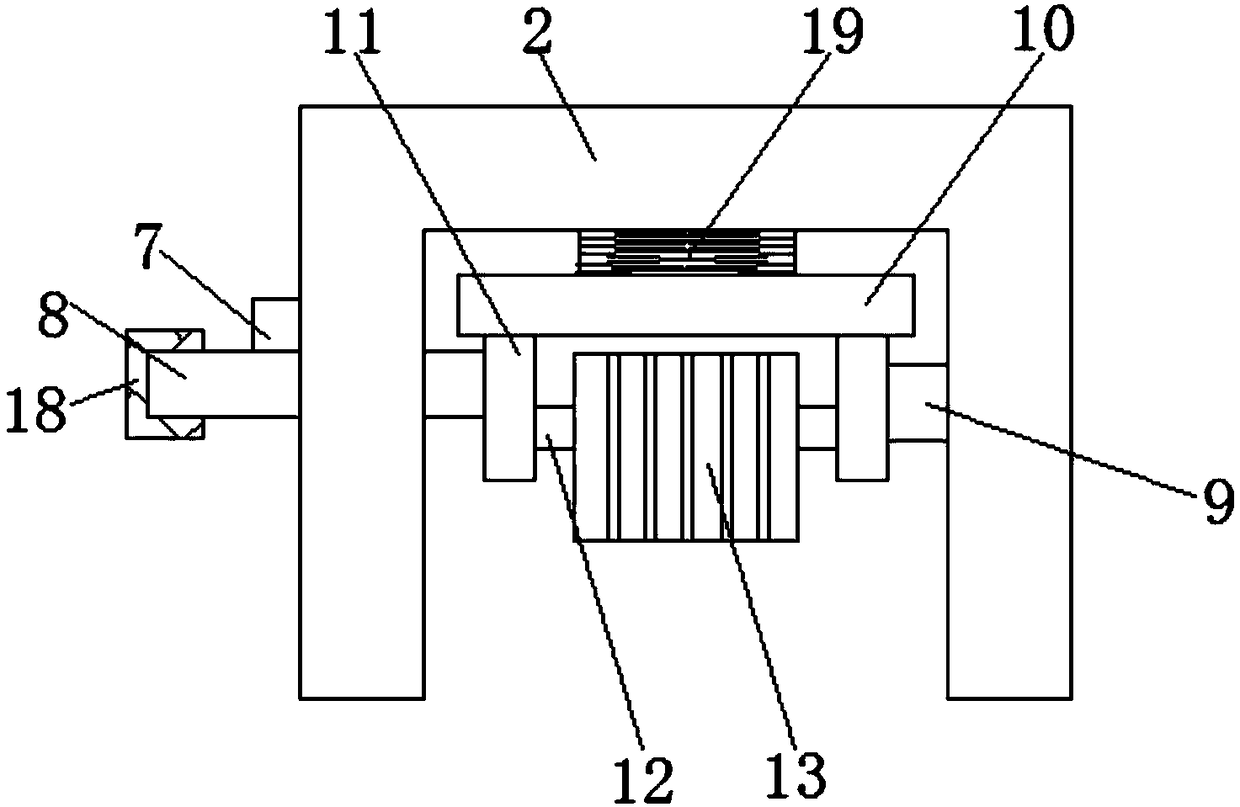
[0016] see Figure 1-3 , a power distribution cabinet that is easy to move, including a power distribution cabinet body 1, the outer surface of the power distribution cabinet body 1 is fixedly connected with a warning strip 14, which plays a role of reminder and warning, avoids accidental electric shock caused by personnel touching, and improves the overall safety. Reliability, the bottom of the power distribution cabinet body 1 is fixedly connected with four ...


PUM


Abstract

The invention discloses an electric power distribution cabinet convenient to move. The electric power distribution cabinet includes an electric power distribution cabinet body. Four fixed blocks arranged in an equidistant way are fixedly connected to the bottom of the electric power distribution cabinet body. Symmetrical heat emission holes are arranged in the external surface of the electric power distribution cabinet body. An annular holding rod is arranged on one end, being close to the heat emission holes, of the electric power distribution cabinet body. The inner wall of the annular holding rod is fixedly connected to the external surface of the electric power distribution cabinet body. A bar-shaped through hole is arranged in one side surface, being close to the heat emission holes,of each fixed block. Symmetrical screw holes are arranged in one side surface, being close to each bar-shaped through hole, of each fixed block. Positioning screws are threadedly connected to the inner part of the screw hole. A pressing bar is arranged on one side of each fixed block. One end of each pressing bar passes through each fixed block and extends to the inside of each fixed block. The external surfaces of the positioning screws contact with the bottoms of the pressing bars. A slideway is arranged on the inner wall of each fixed block. According to the invention, the integral body ofthe electric power distribution cabinet is movable, human drag can be avoided, parts inside the electric power distribution cabinet can be prevented from becoming loose, and the normal usage of the electric power distribution cabinet can be ensured.

Description

technical field [0001] The invention relates to the technical field of power distribution cabinets, in particular to a power distribution cabinet that is easy to move. Background technique [0002] The power distribution cabinet (box) is divided into power distribution cabinet (box), lighting distribution cabinet (box), metering cabinet (box), and is the final equipment of the power distribution system. The power distribution cabinet is a general term for the motor control center. The power distribution cabinet is used in the occasions where the load is relatively scattered and there are few circuits. The motor control center is used in the occasions where the load is concentrated and there are many circuits. They distribute the electric energy of a certain circuit of the upper-level power distribution equipment to the nearest load. The equipment should provide protection, monitoring and control for the load. The power distribution cabinet is a massive parameter in the data...

Claims


Application Information

Patent Timeline
Patent Type & Authority Applications(China)
IPC IPC(8): H02B1/30
CPCH02B1/303
Inventor 王在江
Owner 王在江
Why Eureka
Try Eureka