Pairing method and paring system of transmitting end and receiving end under wireless charging scene
A wireless charging and transmitter technology, applied in the field of a transmitter and a receiver pairing method and system, can solve the problems of increasing the purchase cost, equipment installation area, increasing the complexity of the system charging process, low utilization rate of the transmitter, etc. Time to find a unique transmitter location, reduce equipment procurement costs, and reduce equipment installation footprint
- Summary
- Abstract
- Description
- Claims
- Application Information
AI Technical Summary
Problems solved by technology
Method used
Image

Examples
no. 1 example
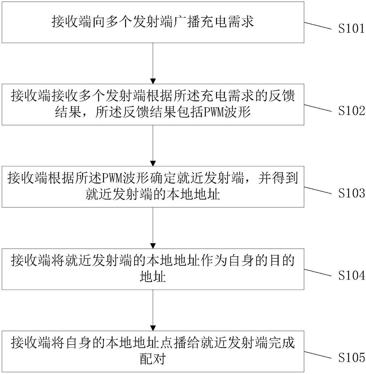
[0033] Such as figure 1 As shown, a first embodiment of a method for pairing a transmitter and a receiver in a wireless charging scenario includes the following steps:
[0034] S101, the receiving end broadcasts charging requirements to multiple transmitting ends;
[0035] S102. The receiving end receives feedback results from a plurality of transmitting ends according to the charging requirement, and the feedback results include PWM waveforms;
[0036] S103, the receiving end determines the nearest transmitting end according to the PWM waveform, and obtains the local address of the nearby transmitting end;
[0037] S104, the receiving end uses the local address of the nearest transmitting end as its own destination address;
[0038] S105, the receiving end broadcasts its own local address to the nearest transmitting end to complete the pairing.
[0039] In this embodiment, no additional sensors and hardware devices are required. Use the coil and wireless communication mod...
no. 2 example
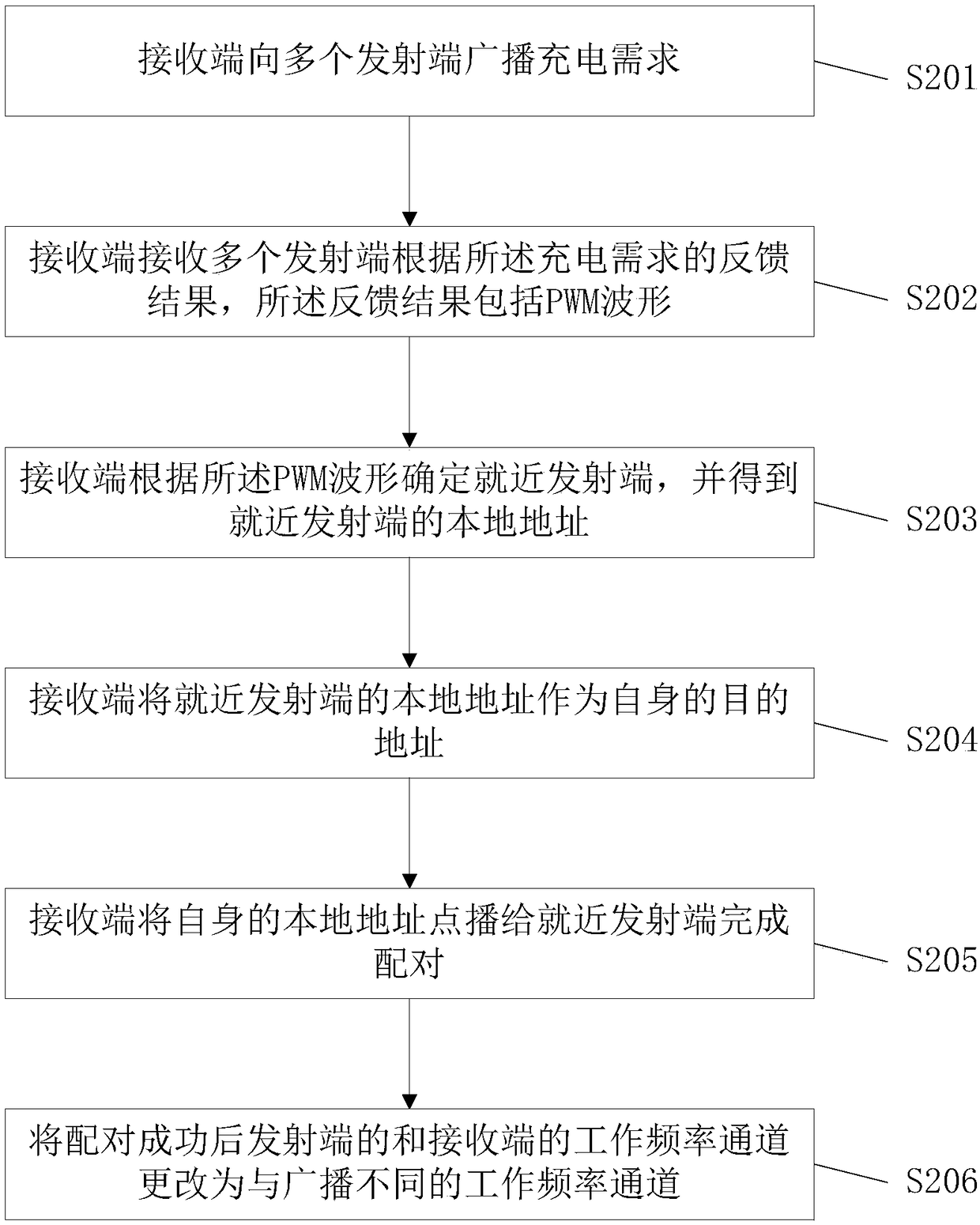
[0041] Such as figure 2 As shown, a second embodiment of a method for pairing a transmitter and a receiver in a wireless charging scenario includes the following steps:
[0042] S201, the receiving end broadcasts charging requirements to multiple transmitting ends.
[0043] Specifically, the wireless communication module I at the transmitting end has a local address I and the destination address I, and the wireless communication module II at the receiving end has a local address II and a destination address II. The local address I of each transmitting end is a specific value defined manually, namely local address Ⅰ 1 , local address I 2 , ..., local address I N . Similarly, the local address II of each receiver is also a specific value defined by humans, that is, the local address II 1 , local address II 2 ,...,local address II N . What needs to be explained is that since the local address I and the local address II are defined artificially, there is no limitation her...
PUM
 Abstract
Description
Claims
Application Information
 - R&D
- Intellectual Property
- Life Sciences
- Materials
- Tech Scout
- Unparalleled Data Quality
- Higher Quality Content
- 60% Fewer Hallucinations
Browse by: Latest US Patents, China's latest patents, Technical Efficacy Thesaurus, Application Domain, Technology Topic, Popular Technical Reports.
© 2025 PatSnap. All rights reserved.Legal|Privacy policy|Modern Slavery Act Transparency Statement|Sitemap|About US| Contact US: help@patsnap.com