Light control module including base and control parts, communicating via nfc

A technology for controlling modules and bases, applied to antenna parts, parts of lighting devices, semiconductor devices of light-emitting elements, etc.

Inactive Publication Date: 2020-04-24
SCHREDER SA
View PDF6 Cites 0 Cited by
  • Summary
  • Abstract
  • Description
  • Claims
  • Application Information

AI Technical Summary

Problems solved by technology

One disadvantage is that the person responsible for ordering the lighting is often not the same person who orders the control modules

Method used


Image

  • Light control module including base and control parts, communicating via nfc
  • Light control module including base and control parts, communicating via nfc
  • Light control module including base and control parts, communicating via nfc

Examples


Embodiment Construction

[0060] Individual technical features of the exemplary embodiments described below can also be combined to form other embodiments according to the present invention in combination with the exemplary embodiments described herein. Furthermore, combinations of the exemplary embodiments with the features of the claims are also consistent with the invention. Elements having the same functional effect have the same reference signs where appropriate.

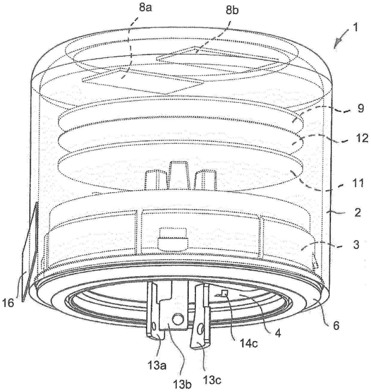
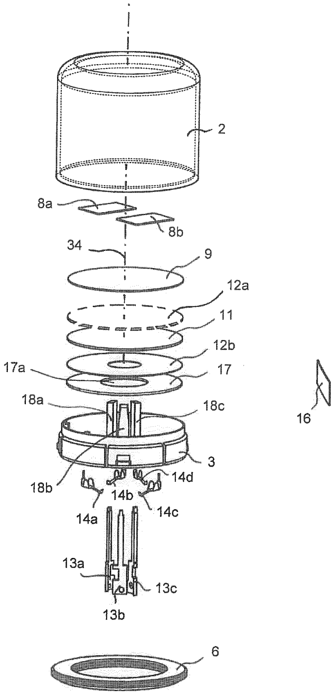
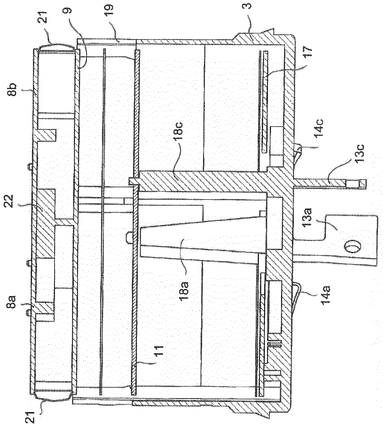
[0061] Figure 1 to Figure 3 A control module 1 according to the invention is shown having a housing comprising an outer housing part or cover 2 and an inner housing part 3 . The end face 4 of the inner housing part 3 is additionally provided with a seal 6 by means of which a connection with the control module base ( Figure 1 to Figure 3 not shown in ) to create an airtight closure.

[0062] A series of components of the control module 1 are schematically shown. These components include the antennas 8a, 8b which may be driven by a ...


PUM


Abstract

The invention describes a control arrangement for mounting on an outer surface of a lighting device. The control arrangement comprises a control module (1) and a control module base configured to be mounted to each other. The control module base includes a near field communication device configured to communicate with a near field communication unit provided in the control module (1).

Description

technical field [0001] The present invention relates to improvements in or relating to control module arrangements. Background technique [0002] The control module arrangement includes a control module and a control module base for securing the control module to the outside of the lighting fixture housing. The use of a control module provides the means by which the luminaire can be integrated into a luminaire network and, furthermore, into a luminaire management system. The control module base has a base body which can be at least partially in the form of a solid body and on which at least one fastening means for fastening the control module on the top side of the base body is arranged. The fastening means may comprise latching means, grooves or threaded connections for complementary latching means of the control module, the fastening means being provided on the top side or surface of the control module base, for example recessed into the top surface of the base or Presen...

Claims


Application Information

Patent Timeline
Patent Type & Authority Patents(China)
IPC IPC(8): H05B47/10
CPCH05B47/19H05B47/195F21V23/0435F21Y2115/10H01Q1/00H01Q1/40H01Q1/526H01Q1/2208H04W4/80
Inventor 赫尔穆特·施罗德丹尼尔·布兰德
Owner SCHREDER SA
Why Eureka
Try Eureka