Multiple Disc Clutch

一种多盘式、离合器的技术,应用在离合器、摩擦离合器、流体驱动离合器等方向,能够解决多片式离合器没有适当地通风等问题,达到减少结构要求的效果

Active Publication Date: 2018-08-03
SCHAEFFLER TECH AG & CO KG
View PDF5 Cites 0 Cited by
  • Summary
  • Abstract
  • Description
  • Claims
  • Application Information

AI Technical Summary

Problems solved by technology

In addition, multi-plate clutches are mostly not properly vented when the friction points between the plates and the plate carrier are not lubricated by oil

Method used


Image

  • Multiple Disc Clutch
  • Multiple Disc Clutch
  • Multiple Disc Clutch

Examples


Embodiment Construction

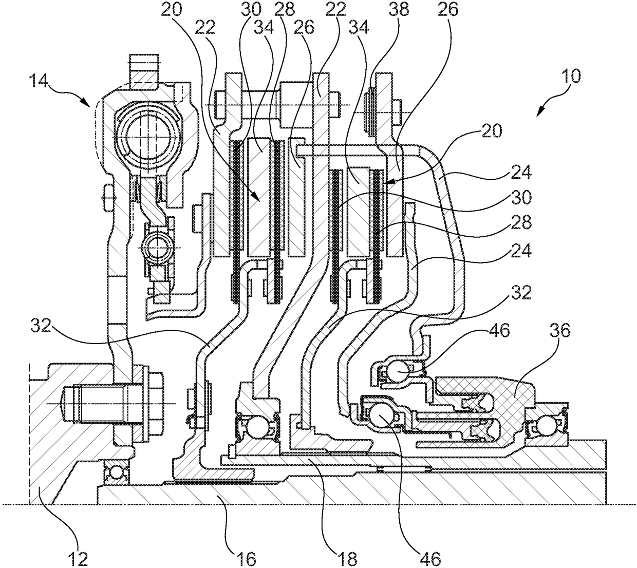
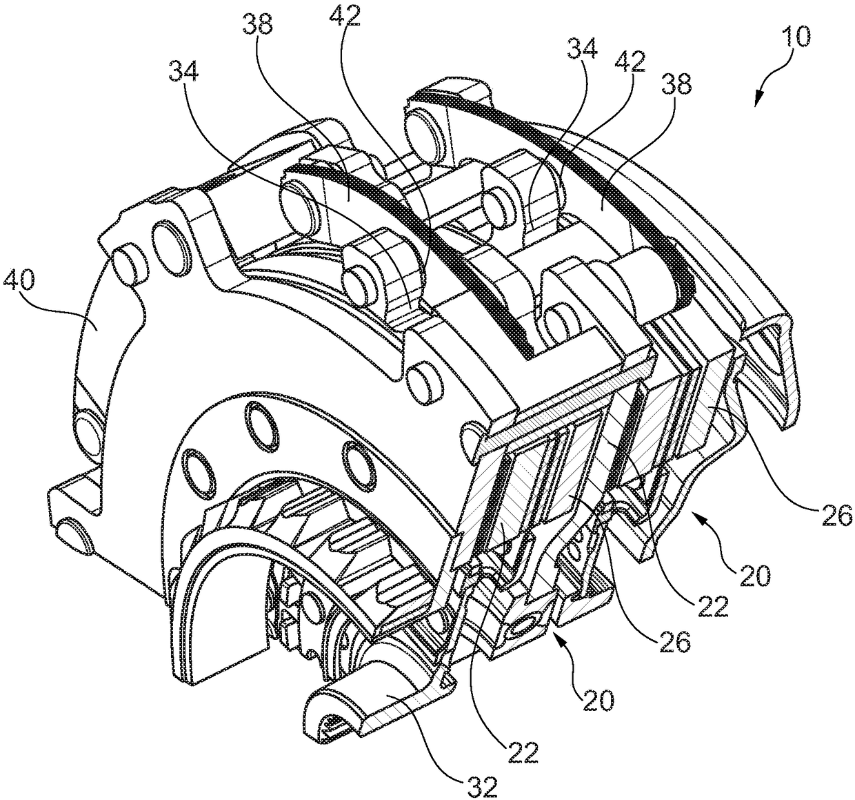
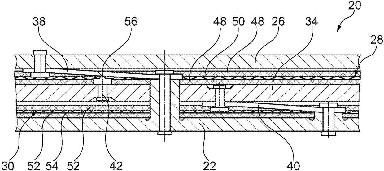
[0051] figure 1 The dual clutch 10 shown in FIG. 2 can decouple a drive shaft 12 from a first transmission input shaft 16 and a second transmission input shaft 18 via a torsional vibration damper 14 designed as a dual-mass flywheel. For this purpose, a multi-disc clutch 20 is provided in each case, each having a corresponding plate 22 coupled to the drive shaft 12 and a pressure plate displaceable by means of an actuating element 24 designed as a rigid actuating pot 26, wherein, the pressing plate 26 can also press the middle plate 34, and the middle plate is arranged between the first lining ring 28 of the clutch disc 32 and the second lining that can move axially relative to the first lining ring 28 Between rings 30. For this purpose, an actuating force, in particular for closing the multidisc clutch 20 , can be introduced into the actuating element 24 by the hydraulic actuating element 36 . The pressure plate 26 is connected at least indirectly to the counter plate 22 via...


PUM


Abstract

A multi-disc clutch, in particular a two-disc clutch, having a counter plate (22), a clutch disc (32) with a first lining ring (28) and a second lining ring (30) and having an intermediate plate (34 ), wherein, there are n intermediate plates (34) and n+1 lining rings (28, 30), wherein the movement of the intermediate plate and the movement of the extrusion plate pass through the coupling mechanism (44) along the Coupling in the axial direction, wherein at least between the open position of the pressure plate corresponding to the open position of the multi-disc clutch and the maximum closed position of the pressure plate corresponding to the closed position of the multi-disc clutch when the lining rings are worn Current travel of the axial displacement of the compression plate relative to the axial displacement of the intermediate plate furthest away from said compression plate in the axial direction at the axial position SA of the compression plate in the section section The conversion ratio i(SA) deviates from i(SA)=n+1, and / or in the case of the axial position SA of the squeeze plate, the axial displacement of the squeeze plate relative to the axial direction of the j-th intermediate plate The shifted current stroke conversion ratio i(SA)j deviates from i(SA)j=(n+1) / j, where j is counted from the corresponding plate towards the squeeze plate. Through the stroke conversion ratio of the coupling mechanism deviating from n+1, the multi-disc clutch can be easily adapted to different design dimensions of the lining ring and / or to the desired different operating modes, so that particularly high torque transmission is possible In various designs of the drive train of the motor vehicle, this is achieved by means of a friction clutch.

Description

technical field [0001] The invention relates to a multi-plate clutch, in particular a two-plate clutch, by means of which a drive shaft of a motor vehicle motor can be coupled to at least one transmission input shaft, wherein the multi-plate clutch is especially suitable for dual clutches. Background technique [0002] According to the current state of the art, dry double clutches usually have one disk per partial clutch. These discs each have two friction surfaces, with which the discs bear against their adjacent components (such as the pressure plate and the central plate or the corresponding plate), if the discs are clamped by the clutch for torque transmission And thus these plates form two friction points with the clutch. The transmissible torque of the clutch can also be increased with the same pressing force, the same diameter and the same friction ratio (friction coefficient) by increasing the number of friction points. This principle is frequently used in multi-pl...

Claims


Application Information

Patent Timeline
Patent Type & Authority Patents(China)
IPC IPC(8): F16D13/54F16D13/70
CPCF16D13/54F16D13/70F16D2013/703F16D21/06F16D2013/706F16D2021/0615F16D2021/0669F16D13/385F16D25/10F16D25/082F16D13/75F16D69/00
Inventor D·赖姆尼茨
Owner SCHAEFFLER TECH AG & CO KG
Why Eureka
Try Eureka