
Liquid-enhanced non-contact mechanical seal structure

A non-contact, mechanical seal technology, applied in the direction of engine seals, mechanical equipment, engine components, etc., can solve the problems of end face wear, high viscosity fluid can not lubricate and dissipate heat, insufficient seal life, etc., to reduce heat generation. , good elastic state, the effect of reducing operating power consumption

Pending Publication Date: 2018-08-31
SICHUAN SUNNY SEAL
View PDF0 Cites 3 Cited by
  • Summary
  • Abstract
  • Description
  • Claims
  • Application Information

AI Technical Summary

Problems solved by technology

However, this kind of seal encounters problems when dealing with high viscosity, a large amount of sediment and other working conditions. A large amount of particles and impurities enter the sealing end face, causing severe wear on the end face, and the high viscosity fluid cannot form effective lubrication and heat dissipation on the end face, resulting in Significantly insufficient seal life

Method used


Image

  • Liquid-enhanced non-contact mechanical seal structure
  • Liquid-enhanced non-contact mechanical seal structure

Examples


Embodiment 1

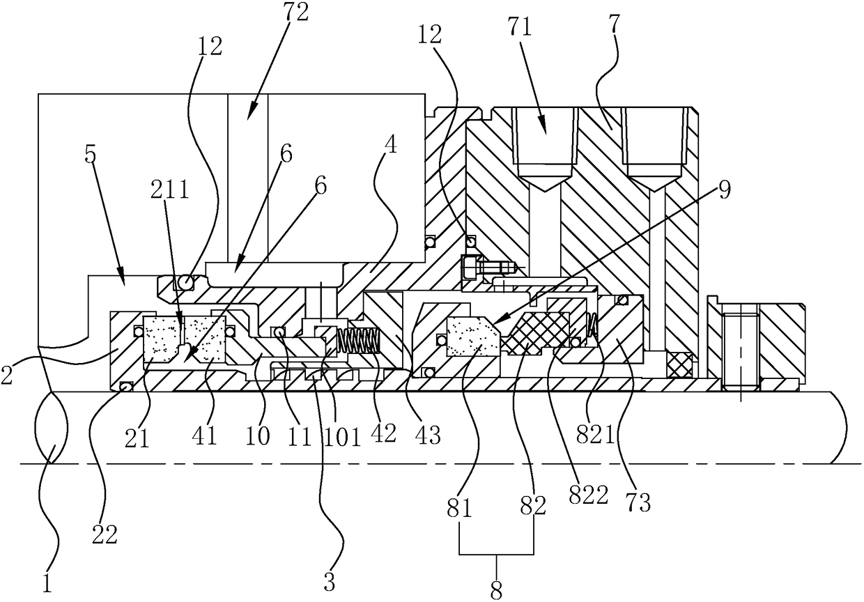
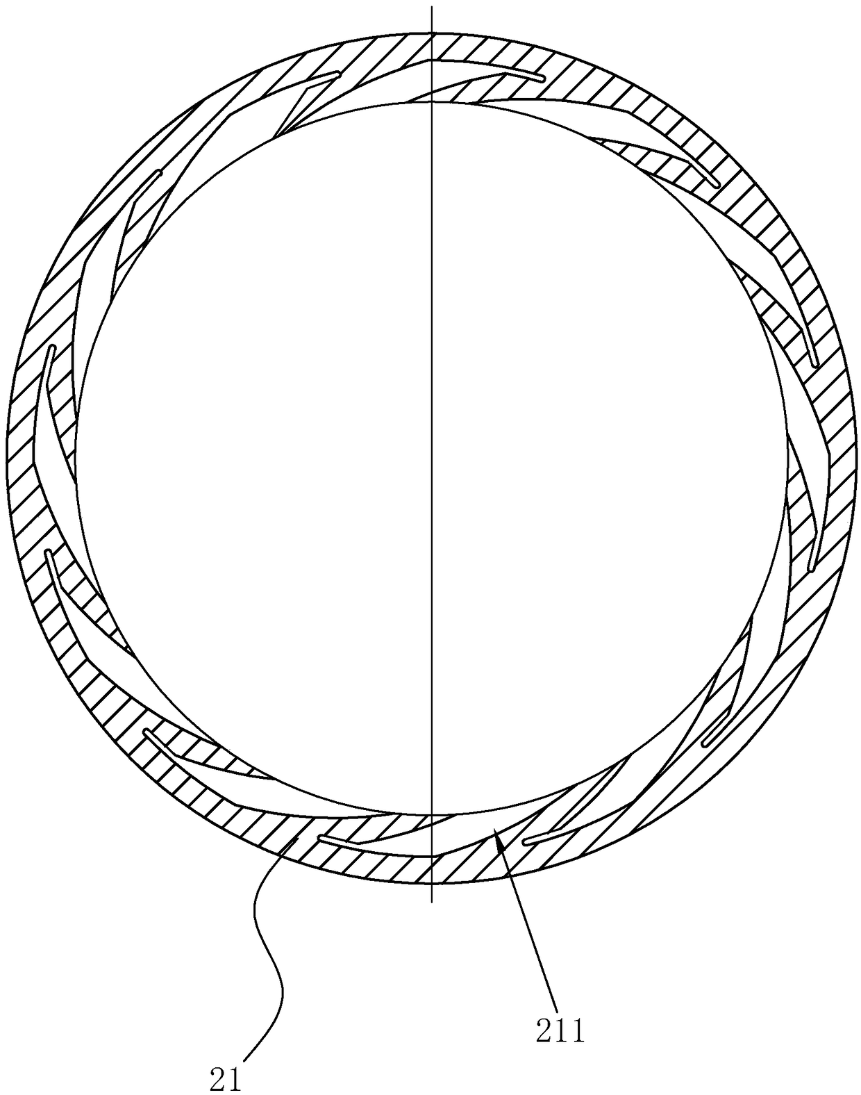
[0033] Such as figure 1 , 2 As shown, a liquid-enhanced non-contact mechanical seal structure includes a sleeve 2 sleeved and fixed on the rotating shaft 1, an inner gland 4 fixed on the pump cavity, and one end of the sleeve 2 is provided with a dynamic The sealing ring 21, the inner gland 4 is provided with a static sealing ring 41 sliding axially along the shaft sleeve 2, the static sealing ring 41 is used for sealing cooperation with the dynamic sealing ring 21; the static sealing ring 41 and the inner gland 4 are arranged There is a first elastic member, and the first elastic member makes the static sealing ring 41 always have a tendency to move toward the moving sealing ring 21 side. The end surface of the dynamic seal ring 21 facing the static seal ring 41 or the end surface of the static seal ring 41 facing the dynamic seal ring 21 is provided with an annular groove 211; in this embodiment, the annular groove 211 is arranged on the inner diameter side of the dynamic s...

Embodiment 2

[0042] The main difference between this embodiment and Embodiment 1 is that: figure 1 , 2 As shown, the ring groove 211 is arranged on the inner diameter side of the static seal ring 41 and communicates with the low-pressure chamber 6. in the opposite direction.

[0043] Specific working process: After the rotating shaft 1 is started to drive the shaft sleeve 2 to rotate, a clean low-pressure liquid is introduced into the inlet 71. At this time, the clean low-pressure liquid circulates in the low-pressure chamber 6 and enters the ring groove 211, and the dynamic sealing ring 21 and the The static sealing ring 41 separates and enters the high-pressure chamber 5, ensuring that the dynamic sealing ring 21 and the static sealing ring 41 always work in a clean fluid, and avoiding the particle impurities or high-viscosity medium in the high-pressure chamber 5 from affecting the sealing operation. The rotating shaft 1 drives the dynamic sealing ring 21 to rotate. Since the dynamic ...


PUM


Abstract

The invention relates to a liquid-enhanced non-contact mechanical seal structure, and relates to the field of mechanical seal. The liquid-enhanced non-contact mechanical seal structure comprises a shaft sleeve, a motive seal ring, an inner pressing cover, a static seal ring and a first elastic part, wherein the shaft sleeve is connect with a rotating shaft in a sleeving mode, and is fixed to the rotating shaft; the motive seal ring is arranged on the shaft sleeve; the inner pressing cover is fixed to a pump cavity body; the static seal ring is arranged on the inner pressing cover in a slidingmode; and the first elastic part is arranged between the static seal ring and the inner pressing cover. A ring groove is formed in the end face of the motive seal ring toward the static seal ring or the end face of the static seal ring toward the motive seal ring. A high-pressure cavity capable of accommodate high-pressure liquid is formed between the outer diameter sides of the motive seal ring and the static seal ring and a cavity. A low pressure cavity capable of accommodating low-pressure liquid is formed between the inner diameter sides of the motive seal ring and the static seal ring andthe shaft sleeve. The shaft sleeve is sleeved with an outer pressing cover, and an inlet and an outlet are formed in the outer pressing cover. A rotating shaft press the clean low-pressure liquid into a circular groove to separate the motive seal ring from the static seal ring, the full liquid film lubrication and contact operation of the seal end face is achieved, and the heat generation is reduced, so that the service life of the seal is greatly prolonged.

Description

technical field [0001] The invention relates to the field of mechanical seals, in particular to a liquid-enhanced non-contact mechanical seal structure. Background technique [0002] A mechanical seal is a shaft seal device for a fluid rotating machine, also known as a face seal. The traditional contact mechanical seal is under the action of the elastic force of the compensation mechanism to make it fully fit, so as to prevent the sealing medium from leaking from the sealing end faces. The friction pair composed of the dynamic / static ring is generally in the state of boundary friction or mixed friction. Under high-parameter conditions (high temperature, high pressure, high speed, etc.), the friction factor is large, the power consumption is high, the wear is serious, and the service life is short. and higher maintenance costs. With the rapid development of aerospace, nuclear power, natural gas transmission and petrochemical industries, higher requirements are put forward f...

Claims


Application Information

Patent Timeline
Patent Type & Authority Applications(China)
IPC IPC(8): F16J15/34F16J15/32
CPCF16J15/32F16J15/34
Inventor 刘小明王泽平张车宁段媛竹陈果
Owner SICHUAN SUNNY SEAL
Features
  • Generate Ideas
  • Intellectual Property
  • Life Sciences
  • Materials
  • Tech Scout
  • Unparalleled Data Quality
  • Higher Quality Content
  • 60% Fewer Hallucinations
Learn More