High-temperature superconductive closing coil constant-current switch structure and work method thereof

A technology of closed coils and constant current switches, which is applied to superconducting magnets/coils, magnetic objects, electrical components, etc., can solve the problems of light weight and compactness of superconducting closed coils that are difficult to highlight, increase volume and weight, The complex structure of superconducting closed coils and other issues have achieved the effects of ensuring safe and stable operation, reducing energy input requirements, and low heat load

Pending Publication Date: 2018-08-31
SHANGHAI JIAO TONG UNIV
View PDF6 Cites 4 Cited by
  • Summary
  • Abstract
  • Description
  • Claims
  • Application Information

AI Technical Summary

Problems solved by technology

At present, whether it is a thermal control, magnetic control or flow control superconducting constant current switch, it needs additional auxiliary equipment to help it realize switching off and on, such as heating wire, magnetic field generating device or external current source, so that the superconducting closed coil The structure of the superconducting closed coil is complicated, and the volume and weight are increased at the same time, which makes it difficult to highlight the advantages of the original light weight and compactness of the superconducting closed coil

Method used


Image

  • High-temperature superconductive closing coil constant-current switch structure and work method thereof
  • High-temperature superconductive closing coil constant-current switch structure and work method thereof
  • High-temperature superconductive closing coil constant-current switch structure and work method thereof

Examples


Embodiment Construction

[0037] The present invention will be described in detail below in conjunction with specific embodiments. The following examples will help those skilled in the art to further understand the present invention, but do not limit the present invention in any form. It should be noted that those skilled in the art can make several changes and improvements without departing from the concept of the present invention. These all belong to the protection scope of the present invention.

[0038] The switching speed of conventional superconducting constant current switches is slow. Traditional superconducting constant current switches, especially the thermally controlled type widely used at present, take time to heat up and cool down the heating wire, which leads to slow turn-on and turn-off speeds, and is difficult to apply to occasions that require frequent switching.

[0039] (1) The switching of traditional superconducting constant current switches requires additional auxiliary equipm...


PUM

PropertyMeasurementUnit
electrical resistivityaaaaaaaaaa
critical temperatureaaaaaaaaaa

Abstract

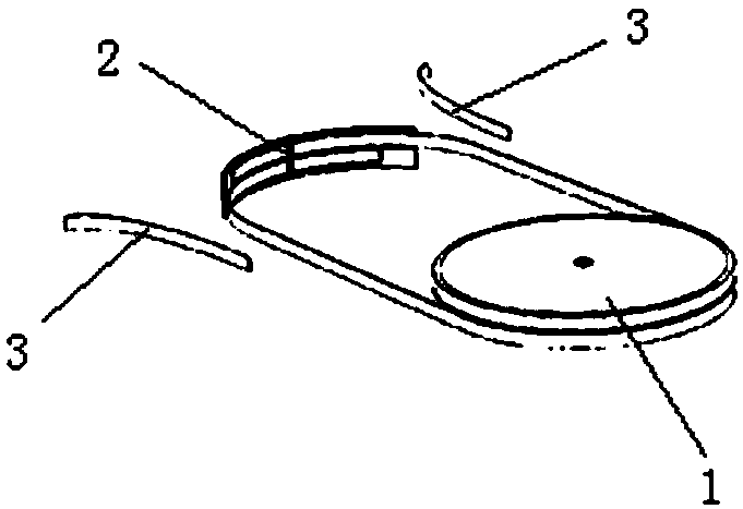
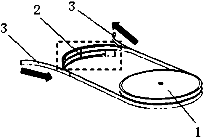
The invention provides a high-temperature superconductive closing coil constant-current switch structure and a work method thereof. The high-temperature superconductive closing coil constant-current switch structure comprises a switch body and a lead, and the switch body is connected with a closing coil to form a closed circuit. The lead is connected with the switch body and an exciting current source. Compared with the prior art, the high-temperature superconductive closing coil constant-current switch structure has the advantages that the size and weight of the superconductive closing coil can be reduced, the aim of compaction and weight reduction is achieved, and the high-temperature superconductive closing coil constant-current switch structure is especially suitable for magnetically levitated trains or aircrafts or other occasions with strict requirements on the size and weight; a switch-off resistor of the switch is dynamically changing, heating and exciting can be balanced well,successful exciting is achieved, and meanwhile the heat load of a refrigerating system is reduced to the minimum; turning off of the switch does not need to be controlled by other additional equipment, and therefore external equipment does not need to be driven by additional energy to work. Therefore, the energy input need of a whole closing superconductive coil system can be reduced, and the high-temperature superconductive closing coil constant-current switch structure is more suitable for being used on mobile devices.

Description

technical field [0001] The invention relates to a high-temperature superconducting closed-coil constant-current switch structure and a working method thereof which are directly switched off by the over-current control of an excitation current source. Background technique [0002] (1) Characteristics of high temperature superconductors [0003] In 1908, Kamerlingh Onnes, a professor at the University of Leiden in the Netherlands, successfully liquefied helium (He) after many experiments, which also marked that the lowest temperature available to humans has reached 4.2K. Three years later, Professor Onnes discovered that the resistance of mercury (Hg) suddenly dropped to zero at the temperature of liquid nitrogen. This marks that the superconducting phenomenon and superconducting technology have entered the history of human scientific research. Subsequently, Professor Onnes conducted follow-up experiments and confirmed that at a temperature of 4.2K, the resistivity of mercur...

Claims


Application Information

Patent Timeline
Patent Type & Authority Applications(China)
IPC IPC(8): H01F6/06
CPCH01F6/06
Inventor 董方亮黄振郝鲁宁
Owner SHANGHAI JIAO TONG UNIV
Why Eureka
Try Eureka