Planar motion platform for use in optoelectronic packaging

A motion platform, plane motion technology, applied in circuits, electrical components, transportation and packaging, etc., can solve the problems of increasing the load of linear motors, the influence of motion speed, acceleration and start-stop accuracy, and reducing the efficiency and accuracy of optoelectronic packaging. Small size, overcomes the effect of larger size

Inactive Publication Date: 2018-08-31
CENT SOUTH UNIV
View PDF7 Cites 3 Cited by
  • Summary
  • Abstract
  • Description
  • Claims
  • Application Information

AI Technical Summary

Problems solved by technology

[0004] The above-mentioned traditional motion platform increases the load corresponding to the linear motor in the Y (or X) direction because the moving components in the X (or Y) direction are mounted on the moving components in the Y (or X) direction, so that the Y (or X) direction corresponds to the linear motor. The movement speed, acceleration and start-stop accuracy of the motor are affected, which in turn reduces the efficiency and accuracy of optoelectronic packaging

Method used


Image

  • Planar motion platform for use in optoelectronic packaging
  • Planar motion platform for use in optoelectronic packaging
  • Planar motion platform for use in optoelectronic packaging

Examples


Embodiment Construction

[0025] The specific implementation manners of the present invention will be further described in detail below in conjunction with the accompanying drawings and embodiments. The following examples are used to illustrate the present invention, but are not intended to limit the scope of the present invention.

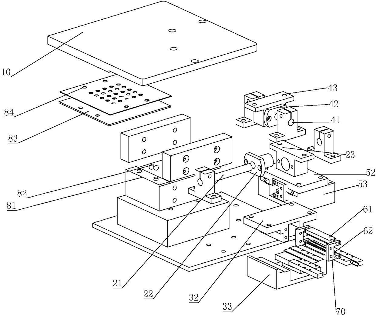
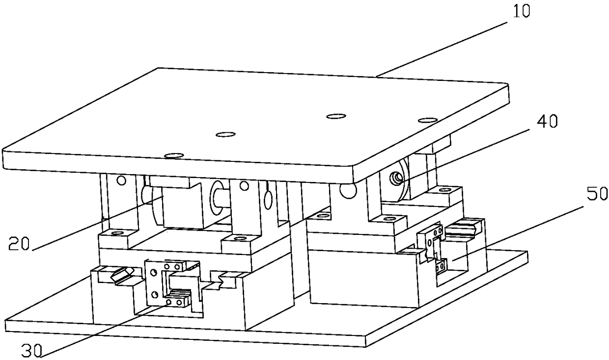
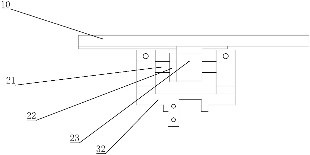
[0026] According to one aspect of the present invention, a planar motion platform applied to optoelectronic packaging is provided. figure 1 It is an exploded diagram of a planar motion platform applied to optoelectronic packaging according to an embodiment of the present invention, figure 2 It is a schematic diagram of a planar motion platform applied to optoelectronic packaging according to an embodiment of the present invention. The motion platform includes: a stage 10, a first decoupling device 20, a first drive device 30, a second decoupling device 40 and a second drive device 50; the top of the first decoupling device 20 is connected to the load The bottom of the o...


PUM


Abstract

The present invention provides a planar motion platform for use in an optoelectronic packaging, comprising: a stage, a first decoupling device, a first driving device, a second decoupling device, anda second driving device; and the top of the first decoupling device and the top of the second decoupling device are connected to the bottom of the stage, the bottom of the first decoupling device is connected to the top of the first driving device, and the bottom of the second decoupling device is connected to the top of the second driving device. The first driving device drives the first decoupling device to drive the first decoupling device to move the stage in the first direction, and the second driving device drives the second decoupling device to drive the second decoupling device to movethe stage in the second direction. It is not necessary to mount the moving member in one direction on the moving member in the other direction, so that the load of the linear motor corresponding to the other direction is prevented from being increased, and the moving speed, acceleration and the start and stop precision of the linear motor corresponding to the other direction are protected from being influenced.

Description

technical field [0001] The invention relates to the technical field of optoelectronic packaging, and more particularly, to a planar motion platform applied to optoelectronic packaging. Background technique [0002] Optoelectronic devices are the core devices in optical fiber communication, and they need to be connected to the input array optical fiber and output array optical fiber respectively during specific use. The connection between the optoelectronic device and the input array optical fiber and the output array optical fiber is an optoelectronic package. Optoelectronic packaging is the process of optically aligning and coupling optoelectronic devices with input array fibers or output array fibers using the load clamping mechanism on the motion platform. Among them, the motion speed, acceleration and start-stop accuracy of the motion platform determine the efficiency and accuracy of optoelectronic packaging. [0003] The traditional motion platform often used in the p...

Claims


Application Information

Patent Timeline
Patent Type & Authority Applications(China)
IPC IPC(8): H01L21/677
CPCH01L21/677
Inventor 周海波张威段吉安侯富龙孔志平
Owner CENT SOUTH UNIV
Why Eureka
Try Eureka