
Traffic restriction method of urban road during specific time period

A technology for specific time periods and urban roads, applied to roads, roads, restricted traffic, etc., can solve the problems of increasing the labor intensity of management personnel and inconvenience of management personnel

Pending Publication Date: 2018-08-31
HUAIYIN INSTITUTE OF TECHNOLOGY
View PDF18 Cites 3 Cited by
  • Summary
  • Abstract
  • Description
  • Claims
  • Application Information

AI Technical Summary

Problems solved by technology

Due to the limitation of the structure, the existing vehicle restriction equipment at the entrance of urban roads can only work in one mode. For example, during the day, the equipment is manually placed on both sides of the road to close the intersection and prohibit large vehicles or all vehicles from entering urban roads. At night, manual operation moves the equipment away from both sides of the road to allow small or all vehicles to enter. The above mode requires that the road does not allow large or all vehicles to enter for a long time, that is to say, when the intersection is closed for a long time, it does not need to open or close the intersection frequently. It can still be used normally and will not cause operational inconvenience to the management personnel. When the intersection needs to be closed and opened for a certain period of time every day, the frequent operation will undoubtedly increase the labor intensity of the management personnel and cause inconvenience to the management personnel.

Method used


Image

  • Traffic restriction method of urban road during specific time period
  • Traffic restriction method of urban road during specific time period
  • Traffic restriction method of urban road during specific time period

Examples


Embodiment Construction

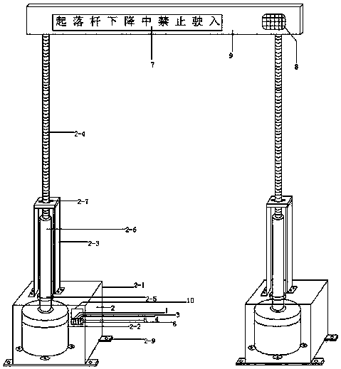
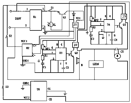
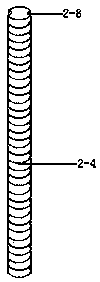
[0019] figure 1 , 3 As shown in , an urban road restricting device for a specific time period includes a switching power supply 1, an electric lifting mechanism 2, a light control circuit 3, a time circuit 4, a remote control circuit 5, an action circuit 6, an LED display 7, and a sounder 8. The upper support plate 9 and the component box 10 have the same two sets of electric lifting mechanisms 2. The two sets of electric lifting mechanisms 2 have the same structure. Each set of electric lifting mechanisms 2 includes a lower casing 2-1 and a motor reduction device 2-2. , support frame 2-3, telescopic screw rod 2-4, there is a bearing seat in the middle of the cover at the upper end of the lower housing 2-1, a bearing 2-5 is installed in the bearing seat, and a bearing 2-5 is welded on the upper end of the output shaft of the motor reduction device. The guide tube 2-6 of the internal thread, the motor deceleration device 2-2 are installed inside the lower housing 2-1, the lowe...


PUM


Abstract

The invention discloses a traffic restriction method of urban roads during a specific time period. The traffic restriction method comprises a switch power source, two sets of same electric lifting mechanisms, a light control circuit, a time circuit, a remote control circuit, an action circuit, an LED display screen, a buzzer, an upper support plate and an element box; the switch power source, thelight control circuit, the time circuit, the remote control circuit and the action circuit are arranged in the element box and are connected with the LED display screen, the buzzer, motors of the electric lifting mechanisms through leads; the upper support plate is arranged at the upper ends of the two sets of the electric lifting mechanism; the LED display screen and the buzzer are arranged at the front end of the upper support plate. The traffic restriction method of urban roads during the specific time period can close road intersections automatically at night, can open the intersections automatically at daytime, and can close the intersections during a required set time period and open the intersections during the rest time period; and a remote-end manager can control the opening and closing the roads through a mobile phone at any time, so that no manager is needed to operate on the site, operational troubles of the managers are reduced, and one mobile phone with multiple functionsis realized.

Description

technical field [0001] The invention relates to the field of automatic control equipment, in particular to a traffic limiting device for a specific time period of an urban road. Background technique [0002] On urban roads, in order to prevent traffic jams, it is often necessary to install vehicle restriction equipment at the entrance of some roads, some roads only allow small motor vehicles to enter, and some roads prohibit all motor vehicles from entering; in practical applications, in order to facilitate transportation Cargo vehicles enter the urban area, so it is often necessary to open the road when there is less traffic and people (such as at night), so that the vehicles can deliver the goods to the merchants along the road. Due to the limitation of the structure, the existing vehicle restriction equipment at the entrance of urban roads can only work in one mode. For example, during the day, the equipment is manually placed on both sides of the road to close the inters...

Claims


Application Information

Patent Timeline
IPC IPC(8): H04L29/08G08C17/02E01F13/04
CPCH04L67/025H04L67/12G08C17/02E01F13/048
Inventor 白秋产金春霞杜董生王马华夏鑫张新荣
Owner HUAIYIN INSTITUTE OF TECHNOLOGY
Learn More