
Automatic vibration disc body welding equipment

An automatic welding and vibrating plate technology, which is applied in welding equipment, welding equipment, auxiliary welding equipment, etc., can solve the problems of waste of heat energy in welding fume, inability to perform double-sided welding, and low welding efficiency, so as to avoid waste of heat energy and improve welding Good effect, the effect of improving welding efficiency

Active Publication Date: 2021-01-05
萍乡市铛铛自动化科技有限公司
View PDF7 Cites 3 Cited by
  • Summary
  • Abstract
  • Description
  • Claims
  • Application Information

AI Technical Summary

Problems solved by technology

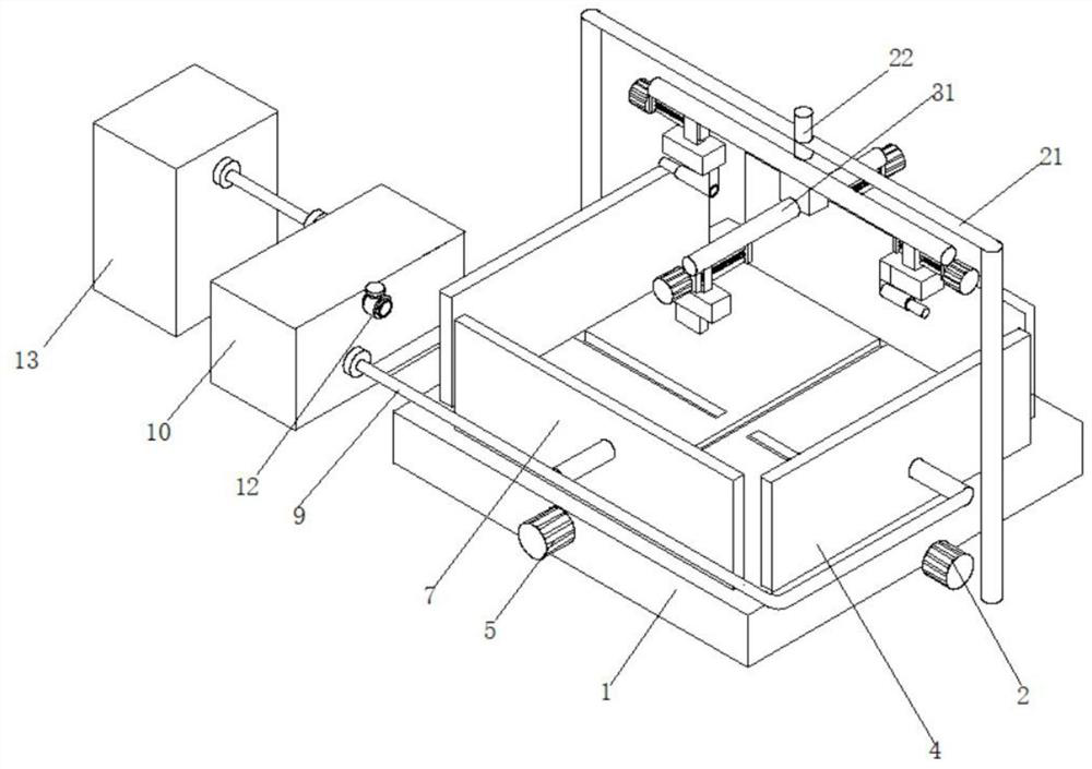
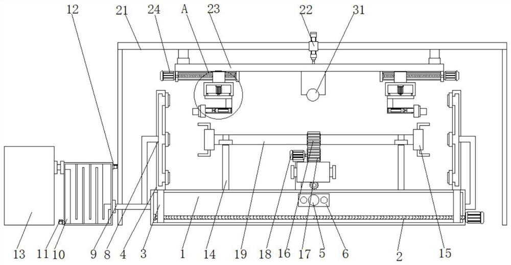
[0004] The purpose of the present invention is: in order to solve the problem that the existing automatic welding equipment for the vibration plate body can only weld one group at a time, the welding speed is slow, and the welding efficiency is low, and the existing automatic welding equipment for the vibration plate body cannot perform double-sided welding. Surface welding needs to remove the workpiece and fix it again, which is cumbersome to operate, and the harmful fume generated by the existing automatic welding equipment for the vibration plate body cannot be processed after heat exchange, resulting in the waste of heat energy of the welding fume. Provide an automatic welding equipment for vibration plate body

Method used


Image

  • Automatic vibration disc body welding equipment
  • Automatic vibration disc body welding equipment
  • Automatic vibration disc body welding equipment

Examples


Embodiment Construction

[0024] The following will clearly and completely describe the technical solutions in the embodiments of the present invention with reference to the accompanying drawings in the embodiments of the present invention. Obviously, the described embodiments are only some, not all, embodiments of the present invention. Based on the embodiments of the present invention, all other embodiments obtained by persons of ordinary skill in the art without making creative efforts belong to the protection scope of the present invention.

[0025] In the description of the present invention, it should be noted that the terms "center", "upper", "lower", "left", "right", "vertical", "horizontal", "inner", "outer" etc. The indicated orientation or positional relationship is based on the orientation or positional relationship shown in the drawings, and is only for the convenience of describing the present invention and simplifying the description, rather than indicating or implying that the referred d...


PUM


Abstract

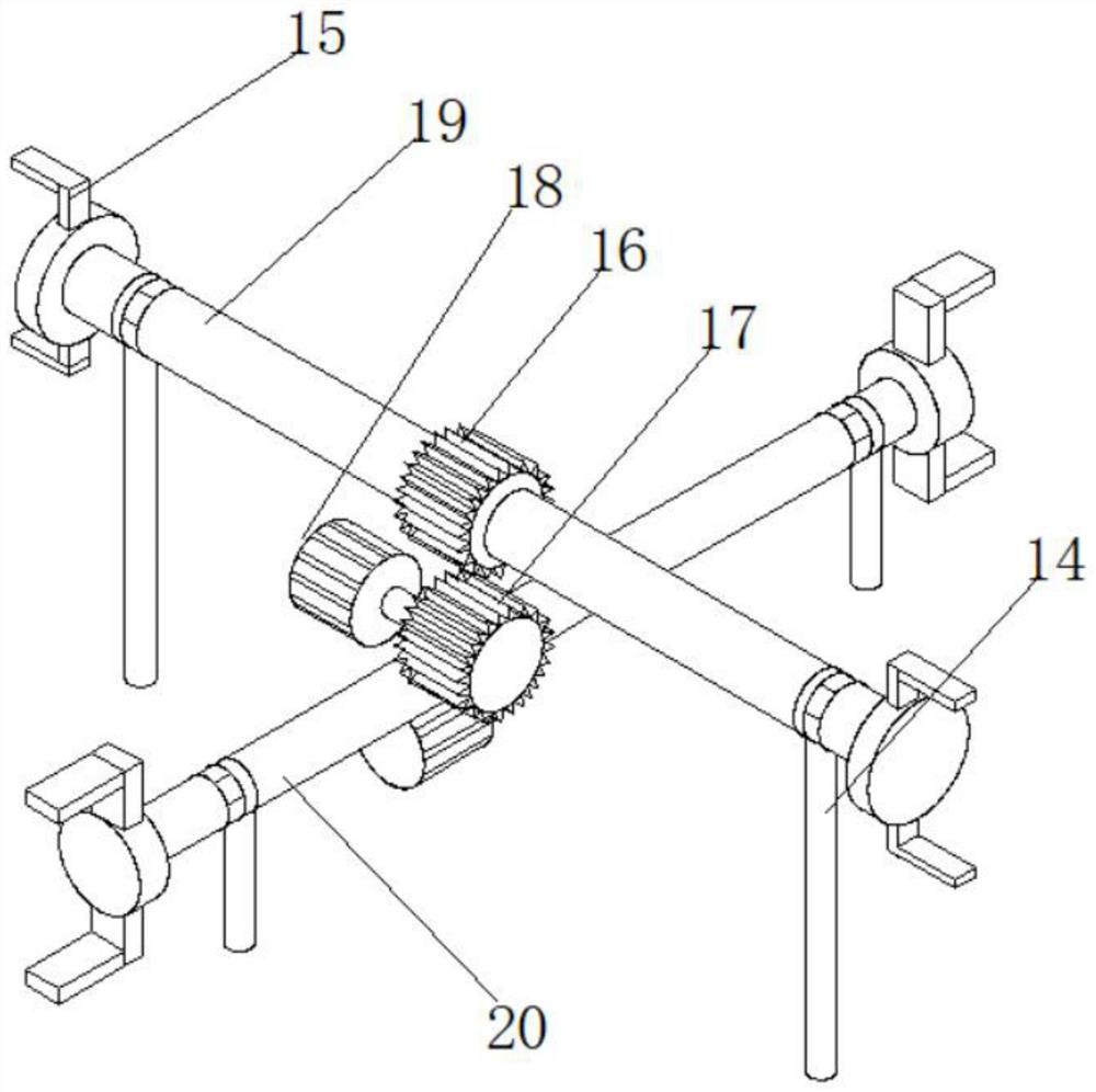
The invention discloses automatic vibration disc body welding equipment, and relates to the field of vibration discs. The automatic vibration disc body welding equipment comprises a bottom plate, wherein a first lead screw is arranged in the bottom plate, a first sliding block is arranged on the outer side of the first lead screw, a first baffle is connected to the top end of the first sliding block, and a second lead screw is arranged at the position, above the first lead screw, in the bottom plate; and a second sliding block is arranged on the outer side of the second lead screw, a second baffle is connected to the top end of the second sliding block, and smoke suction heads are arranged on one side of the second baffle and one side of the first baffle. Through the arrangement of a supporting rod, clamping jaws, a first gear, a second gear, a first motor, a transverse rotating rod, a longitudinal rotating rod, a mounting frame, an air cylinder, a transverse fixing rod and a longitudinal fixing rod, four sets of workpieces are clamped through the four sets of clamping jaws in different directions instead of being welded one by one during welding, and then four sets of welding gunsare used for welding, so that the welding time consumption is reduced, and the welding efficiency is improved.

Description

technical field [0001] The invention relates to the field of vibrating discs, in particular to an automatic welding device for a vibrating disc body. Background technique [0002] The vibrating plate is an auxiliary feeding device for automatic assembly or automatic processing machinery, referred to as the part feeding device. The working principle of the vibrating plate is: frequency converter, motor, and automatic conveying. The vibrating plate is an auxiliary feeding device for automatic assembly or automatic processing machinery Equipment, which can arrange various products in an orderly manner, cooperate with automatic assembly equipment to assemble all parts of the product into a complete product, or cooperate with automatic processing machinery to complete the processing of workpieces. [0003] The existing automatic welding equipment for the vibration plate body can only weld one group at a time, the welding speed is slow, and the welding efficiency is low, and the e...

Claims


Application Information

Patent Timeline
Patent Type & Authority Applications(China)
IPC IPC(8): B23K31/02B23K37/00B23K37/02B23K37/04B08B15/04
CPCB23K31/02B23K37/00B23K37/0252B23K37/0435B08B15/04
Inventor 贺晓钢周锴
Owner 萍乡市铛铛自动化科技有限公司
Learn More