Welding device and welding method for bead-shaped thermistor and wire

A thermistor and welding device technology, applied in auxiliary devices, welding equipment, metal processing, etc., can solve the problems of easy passivation of the nickel-plated protective layer, difficult operation, and overall damage to the head surface, so as to improve the unit Improve the welding success rate and production efficiency, reduce the difficulty of operation, and reduce the effect of welding time

Pending Publication Date: 2021-06-11
航天科工空间工程发展有限公司
View PDF9 Cites 0 Cited by
  • Summary
  • Abstract
  • Description
  • Claims
  • Application Information

AI Technical Summary

Problems solved by technology

[0004] The size of the bead thermistor is small (the head is only a few millimeters), light weight (usually less than 1g), the lead wire is thin (the common wire diameter is only 0.3mm), and the nickel-plated protective layer on the surface of the lead wire is easily passivated. Difficult to tin and not easy to solder
[0005] The head of the bead-shaped thermistor is a key sensitive part and is relatively fragile. When using clip-type fixtures, due to the hardness of the fixture material and the clamping force are not well controlled, damage may occur on the surface of the head or even overall damage, affecting normal operation. use
Even if the lead wire can be clamped and welded by a clamp with a more suitable structure, the metal lead wire at the welding part will swing to a certain extent due to the contact force during the welding process, and the welder must control the relative position of the wire and the lead wire. Tinning and welding state control, the operation is very difficult, and the welding efficiency is low

Method used


Image

  • Welding device and welding method for bead-shaped thermistor and wire
  • Welding device and welding method for bead-shaped thermistor and wire
  • Welding device and welding method for bead-shaped thermistor and wire

Examples


Embodiment Construction

[0034] In order to make the technical solutions and advantages of the present invention clearer, the embodiments of the present invention will be further described in detail below with reference to the accompanying drawings.

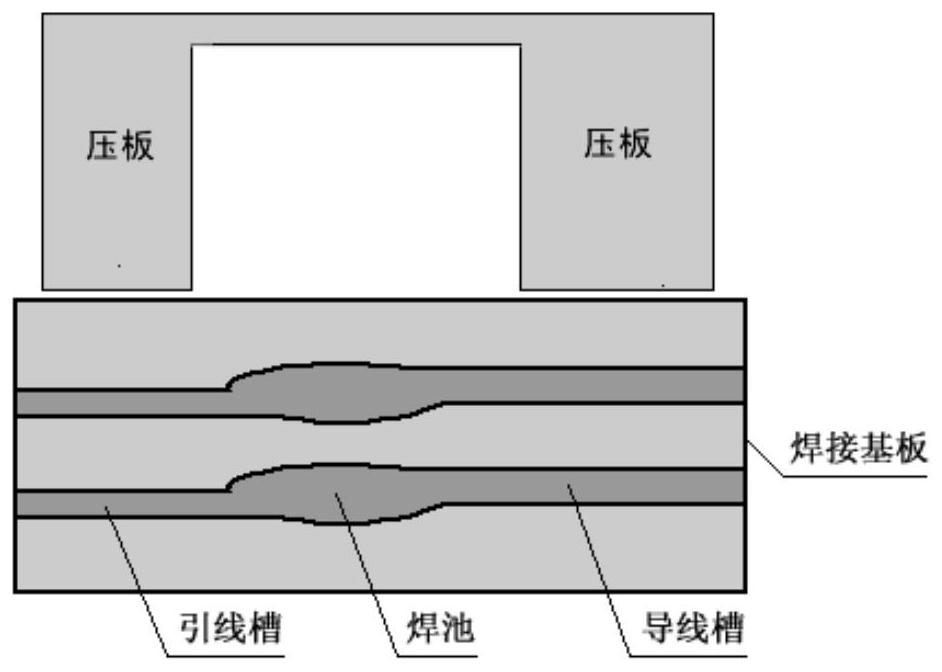
[0035] The first embodiment of the present invention discloses a bead thermistor and a wire welding device, such as image 3 shown, including: soldered base plate and pressure plate, wherein,

[0036] The top surface of the soldering substrate is a plane, and there are 3 grooves connected with each other and the center lines are on the same horizontal plane;

[0037] The pressing plate is used to fix the wires and leads filled in the grooves.

[0038] The centerline of the wireway and wireway needs to have a little horizontal distance so that they just touch to reduce the size of the solder joint.

[0039] In a specific embodiment, the three grooves that communicate with each other are a lead groove, a lead groove and a solder pool, the lead groove is ...


PUM

PropertyMeasurementUnit
Lengthaaaaaaaaaa
Lengthaaaaaaaaaa
Widthaaaaaaaaaa

Abstract

The embodiment of the invention discloses a welding device and a welding method for a bead-shaped thermistor and a wire. The device comprises a welding substrate and a pressing plate, wherein the top surface of the welding substrate is a plane, three grooves which communicating with one another are formed in the welding substrate, and the center lines of the grooves are on the same horizontal plane, and the pressing plate is used for fixing a wire and a lead which are filled in the groove. According to the welding device and the welding method, the operation difficulty of welding the lead and the wire of the bead-shaped thermistor is effectively reduced, the welding time is shortened, the success rate of single-time welding and the production efficiency are improved, the welding effect is better in consistency, and stress damage to the bead-shaped thermistor cannot be generated.

Description

technical field [0001] The present invention relates to the field of electrical equipment technology. More specifically, it relates to a bead thermistor lead and wire welding device and welding method. Background technique [0002] Common bead thermistors have 2 metal leads at the end, which are used to connect to the electrical circuit for temperature measurement. See the schematic diagram. figure 1 . [0003] The way the bead thermistor is connected to the temperature measurement electrical circuit is usually by welding (ie, electric soldering iron + solder) to weld the metal lead to the wire in the circuit, and finally add a layer of heat shrinkable sleeve for electrical insulation. See the schematic diagram. figure 2 . [0004] Bead thermistors are small in size (the head is only a few millimeters), light in weight (usually less than 1g), thin in lead (common wire diameter is only 0.3mm), and the nickel-plated protective layer on the surface of the lead is prone to p...

Claims


Application Information

Patent Timeline
IPC IPC(8): B23K3/00B23K3/08
CPCB23K3/00B23K3/08B23K3/087
Inventor 胡磊
Owner 航天科工空间工程发展有限公司
Why Eureka
Try Eureka