
Easy-to-process automotive engine block fixture

An automotive engine, easy-to-process technology, used in metal processing machinery parts, manufacturing tools, metal processing equipment, etc., can solve the problems of unreliable positioning, inconsistent clamping force of fixtures, unreliability, etc., and achieve reliable and stable clamping. The effect of consistent clamping force

Active Publication Date: 2019-09-10
WUHAN HONGBOXIN PRECISION MACHINERY IND & TRADE CO LTD
View PDF4 Cites 1 Cited by
  • Summary
  • Abstract
  • Description
  • Claims
  • Application Information

AI Technical Summary

Problems solved by technology

In the process of clamping the automobile engine block with the traditional fixture, there are problems such as inconsistent clamping force, unreliability, instability, etc., and it is easy to generate partial load, resulting in low machining accuracy of the automobile engine block. Manually debugging the fixture, It will lead to low processing efficiency and waste of human resources
Moreover, the size of the locating pins in the fixture is fixed, causing the locating pins to be unable to adapt to the positioning holes of different sizes of the automobile engine block, resulting in unreliable positioning; to match a variety of locating holes of different sizes, it is necessary to be equipped with multiple sizes of positioning holes. Positioning pins cause waste of resources

Method used


Image

  • Easy-to-process automotive engine block fixture
  • Easy-to-process automotive engine block fixture
  • Easy-to-process automotive engine block fixture

Examples


Embodiment Construction

[0035] The present invention will be further described in detail below in conjunction with the accompanying drawings, so that those skilled in the art can implement it with reference to the description.

[0036] It should be noted that the experimental methods described in the following embodiments, unless otherwise specified, are conventional methods, and the reagents and materials, if not otherwise specified, can be obtained from commercial sources; in the description of the present invention, The terms "landscape", "portrait", "top", "bottom", "front", "rear", "left", "right", "vertical", "horizontal", "top", "bottom", The orientation or positional relationship indicated by "inner", "outer", etc. is based on the orientation or positional relationship shown in the drawings, which is only for the convenience of describing the present invention and simplifying the description, and does not indicate or imply that the referred device or element must have Certain orientations, co...


PUM


Abstract

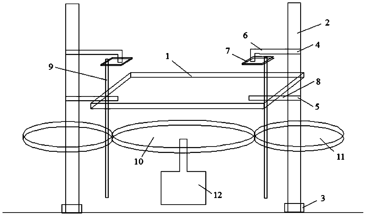
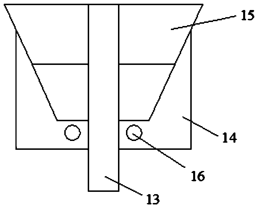
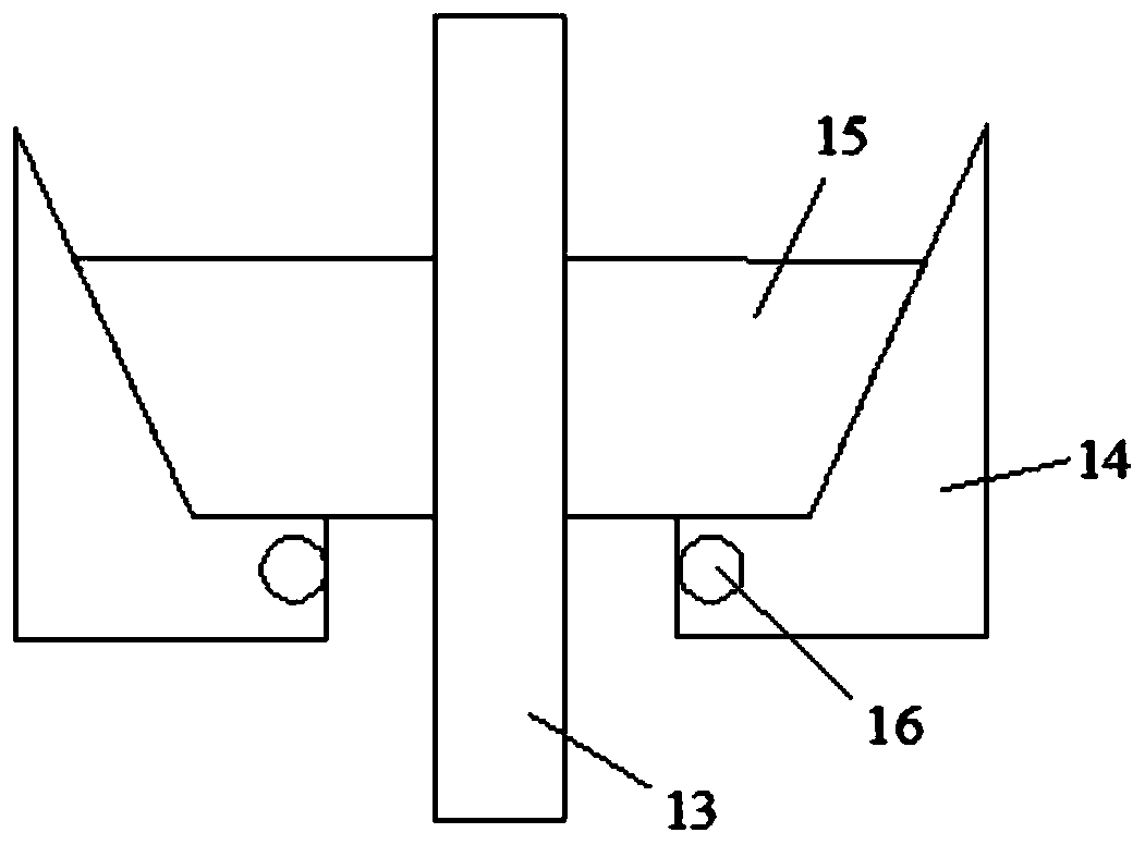
The invention discloses an automobile engine cylinder body clamp facilitating automobile engine cylinder body machining. The clamp comprises a supporting board, a pair of first screw rods, a pair of first through grooves, two pairs of lantern rings, a pair of connecting rods, a pair of fixing rods, a pair of guide columns, a driving gear, a pair of driven gears and two pairs of air cylinders; eachpair of lantern rings comprise the first lantern ring and the second lantern ring, wherein each first lantern ring sleeves the upper part of the corresponding first screw rod and is in threaded connection with the upper part of the corresponding first screw rod, and each second lantern ring sleeves the lower part of the corresponding first screw rod and is in threaded connection with the lower part of the corresponding first screw rod; one ends of the connecting rods are horizontally connected with the first lantern rings corresponding to the first screw rods, and the other end of each connecting rod is vertically downwards connected with a horizontal pressing plate; one sides, close to the first screw rods, of the pressing plates are sunken inwards to form second through grooves; and thelower parts of the guide columns are just clamped in the first through grooves, and the upper parts of the guide columns are just clamped in the second through grooves. The clamp has the advantages of being consistent in clamping force, reliable and stable in clamping, suitable for positioning holes with different sizes and the like, and can be widely applied to the technical field of automobileengine cylinder body clamps.

Description

technical field [0001] The invention relates to the technical field of automobile engine cylinder block clamps, more specifically, the invention relates to an easy-to-process automobile engine cylinder block clamp. Background technique [0002] Fixtures play a very important role in the processing and production of automobile engine blocks, and automobile engine blocks are one of the core components of automobiles. In the process of clamping the automobile engine block with the traditional fixture, there are problems such as inconsistent clamping force, unreliability, instability, etc., and it is easy to generate partial load, resulting in low machining accuracy of the automobile engine block. Manually debugging the fixture, It will lead to low processing efficiency and waste of human resources. Moreover, the size of the locating pins in the fixture is fixed, causing the locating pins to be unable to adapt to the positioning holes of different sizes of the automobile engine...

Claims


Application Information

Patent Timeline
Patent Type & Authority Patents(China)
IPC IPC(8): B23Q3/00
Inventor 周杨波吴浩甘启山
Owner WUHAN HONGBOXIN PRECISION MACHINERY IND & TRADE CO LTD
Learn More