System and method for securing a rotor to a motor drive shaft using a pressure clamp

a technology of pressure clamping and rotor, which is applied in the field of rotors, can solve the problems of inability to reliably achieve maximum clamping force with set screw tightening tools, inaccessible side edges of rotors, and inability to reposition, repair or replace rotors without, so as to reduce the risk of failure, less prone to improper installation, and narrow profile

Active Publication Date: 2009-04-14
NIDEC MOTOR CORP
View PDF1 Cites 1 Cited by
  • Summary
  • Abstract
  • Description
  • Claims
  • Application Information

AI Technical Summary

Benefits of technology

[0012]There are several advantages to the pressure clamp system and method. The principal advantage is (1) that the use of a pressure clamp achieves clamping forces to a motor shaft equal to those found in traditional set screw methods, greater then those of the spoke style, and more consistent and less prone to failure than the split ring with tapered hub method. Other advantages include: (2) the rotor maintains a narrow profile since the present invention does not require any protrusions or components extending out from the rotor; (3) the fasteners used with the pressure clamp are accessible through the faces of the rotor even after the stator housing is mounted on the motor shaft, (4) for a given rotor outer diameter, larger shaft sizes can be accommodated then those using the slotted spoke option, this is partly allowed by the use of hex bolts rather than the traditional Allen head cap screws; and (5) flat and lock washers can be used with these fasteners, which are less susceptible to improper installation by the end user than chemical fasteners typically used with set screw systems and methods.

Problems solved by technology

However, there are disadvantages with each of these current systems.
However, there are several disadvantages with this rotor design.
First, because the magnetic encoder rotor is located inside the stator housing, the side edge of the rotor is inaccessible after mounting the stator housing.
A rotor cannot be repositioned, repaired, or replaced without removing the stator housing.
Second, it is more difficult to reliably achieve maximum clamping force with set screw tightening tools.
For example, it is more expensive to manufacture than using simple set screws.
Further, the clamping forces are inferior to those of set screw methods.
Lastly, the size of motor shaft diameters that can be accommodated are limited by the fact that the space between the slotted spoke and an adjacent spoke must be wide enough for a wrench or other tightening tool to fit.
As with other designs, this system for mounting rotor on a motor shaft is more expensive than a set screw system.
However, this system is subject to assembly errors.
If the clamping screws are not tightened uniformly (or if the screw over the split in the split ring) is tightened first, the clamping force is severely limited.
There may be no immediate external indication of improper clamping, but such an improperly clamped rotor will slip during normal operation and cause system failures.

Method used


Image

  • System and method for securing a rotor to a motor drive shaft using a pressure clamp
  • System and method for securing a rotor to a motor drive shaft using a pressure clamp
  • System and method for securing a rotor to a motor drive shaft using a pressure clamp

Examples


Embodiment Construction

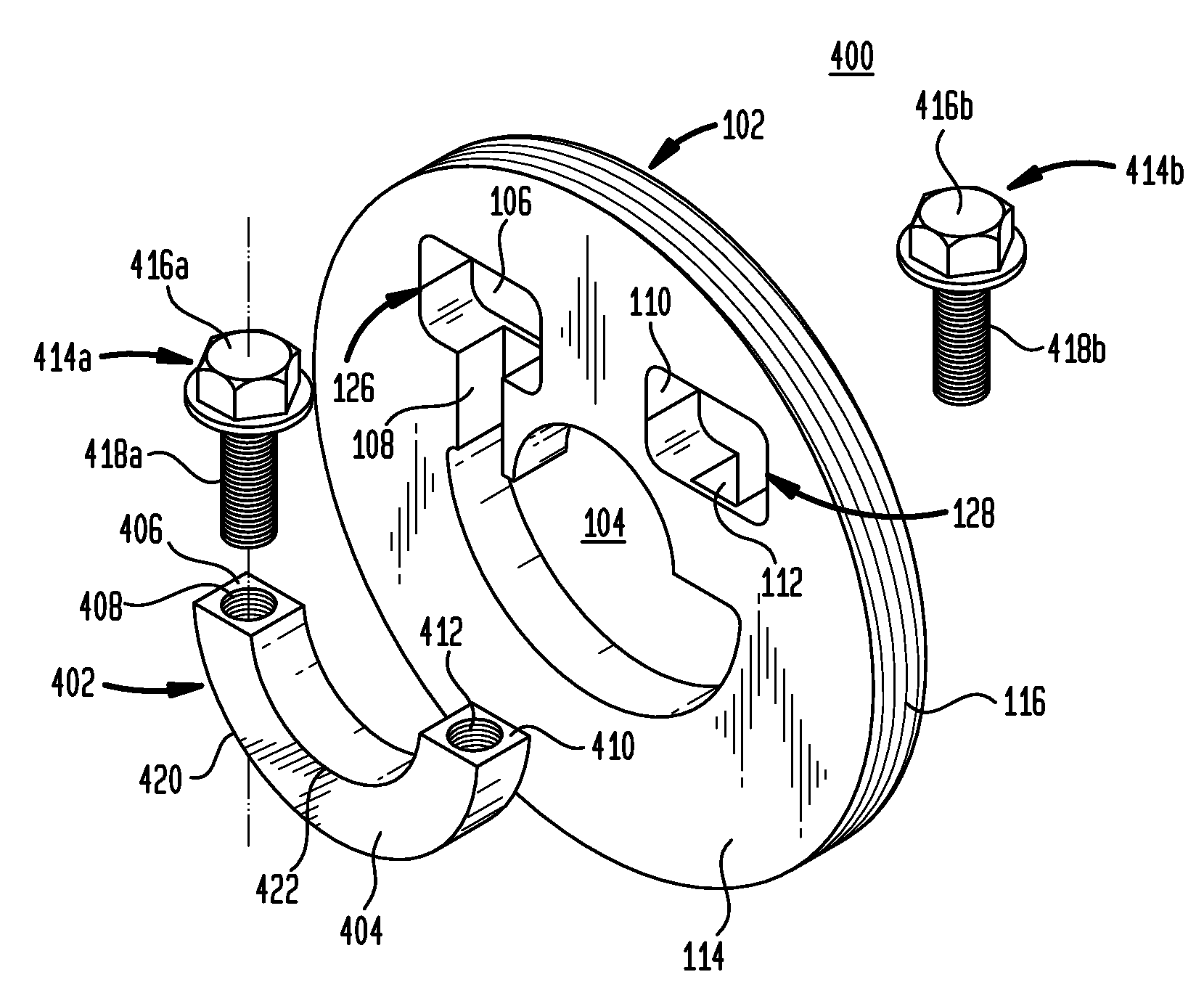
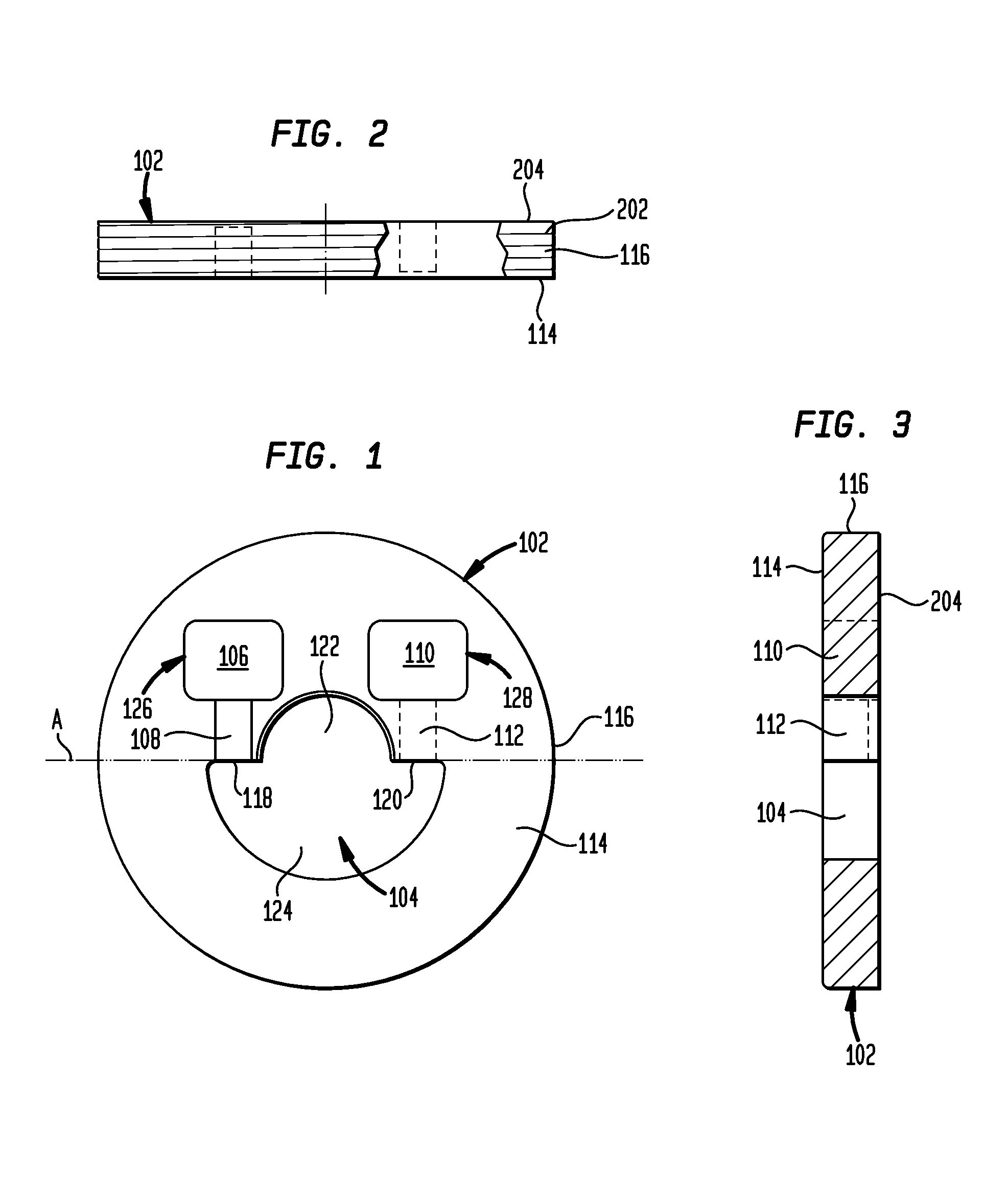
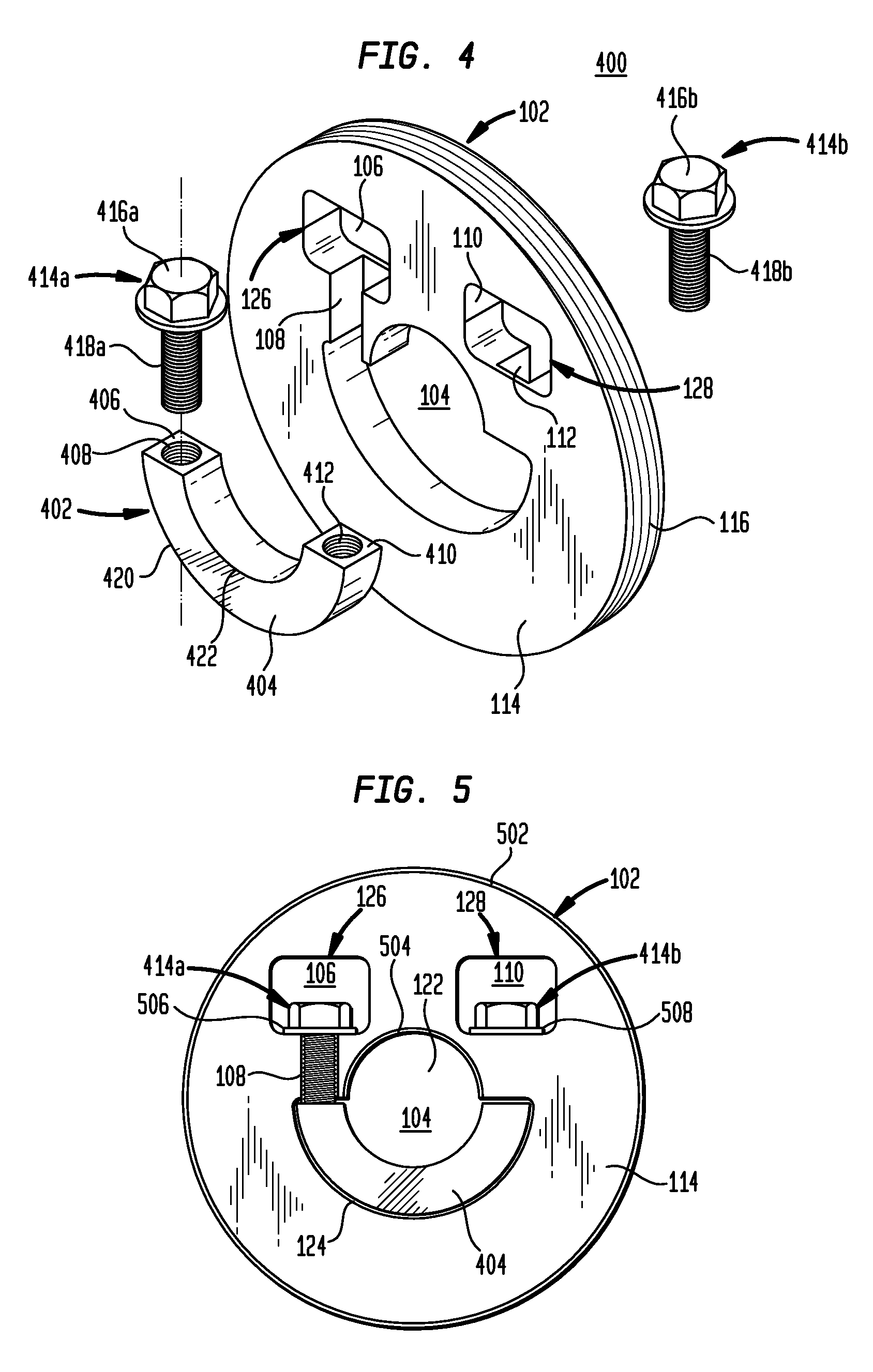
[0022]The rotor assembly of the present invention is shown in the accompanying figures. FIGS. 1-3 show the preferred embodiment of a rotor 102 having a first face 114, a second face 204, an external edge 116, and a main aperture 104 centrally positioned in the rotor 102. The main aperture 104 passes through the entire thickness of the rotor 102 and has a first half 122 and a second half 124. For convenience purpose only, the rotor 102 is shown have a longitudinal axis A that passes through the center point of the rotor 102. Therefore, the first half 122 of the main aperture 104 is that portion of the main aperture 104 located above axis A whereas the second half 124 of the main aperture 104 is that portion of the main aperture 104 located below axis A. In the preferred embodiment, the first half 122 of the main aperture 104 is generally a half circle having a diameter of a first size that is about equal to the diameter of the target motor shaft. The second half 124 of the main apert...


PUM

PropertyMeasurementUnit
diameteraaaaaaaaaa
diameteraaaaaaaaaa
diameteraaaaaaaaaa

Abstract

A rotor assembly for mounting a rotor to a motor shaft having a rotor with a main aperture defined by a first half and a second half. A C-shaped collar is disposed into the second half of the main aperture with the motor shaft passing through the first half of the main aperture and the interior curve of the collar. The collar is secured to the rotor by a plurality of fasteners.

Description

BACKGROUND OF THE INVENTION[0001]1. Technical Field[0002]The present invention relates to rotors, and in particular, to a magnetic encoded rotor incorporating a means for securing the rotor to a motor drive shaft, the means incorporating a pressure clamp.[0003]2. Related Art[0004]There are various systems and methods for mounting modular magnetic encoder rotors to a motor drive shaft (or motor shaft). However, there are disadvantages with each of these current systems.[0005]A first system is directed to a rotor having an external hub encircling and extending away from the central aperture. The external hub typically has a diameter less than the outer diameter of the rotor and extends from the face of the hub a relatively short distance. A plurality of set screws are inserted through holes in the hub to engage the motor shaft. Upon tightening, the set screws secure the rotor to the motor shaft. In this embodiment, the external hub is typically positioned external to a stator housing,...

Claims


Application Information

Patent Timeline
Patent Type & Authority Patents(United States)
IPC IPC(8): B23P11/00F16J15/34
CPCF16D1/0829F16D1/0864F16J15/3488F16J15/3464Y10T29/49947
Inventor EMERY, JOHN W.
Owner NIDEC MOTOR CORP
Why Eureka
Try Eureka