Composite-material core-level cover plate for rocket, and preparation method thereof

A composite material core and composite material technology, which is applied in the foam interlayer, composite assembly structure forming, including internal skeleton, large size, rocket core stage cover and its preparation field, can solve the rigidity and stability of the cantilever cable-stayed structure. Poor, cable-stayed ropes make it inconvenient for operators to walk, and there are potential safety hazards, etc., to improve safety, facilitate disassembly, and improve safety.

Active Publication Date: 2018-09-04
AEROSPACE RES INST OF MATERIAL & PROCESSING TECH +1
View PDF4 Cites 5 Cited by
  • Summary
  • Abstract
  • Description
  • Claims
  • Application Information

AI Technical Summary

Problems solved by technology

[0004] At present, the domestic rocket core-level cover plate mainly adopts metal reinforced wall plate structure. Due to the problem of heavy weight, it is usually necessary to use cable-stayed ropes to assemble and disassemble the cover plate. Inconvenience, there are potential safety hazards, and the rigidity and stability of this cantilever cable-stayed structure are also very poor, and the central part deforms greatly under the load

Method used


Image

  • Composite-material core-level cover plate for rocket, and preparation method thereof
  • Composite-material core-level cover plate for rocket, and preparation method thereof
  • Composite-material core-level cover plate for rocket, and preparation method thereof

Examples


preparation example Construction

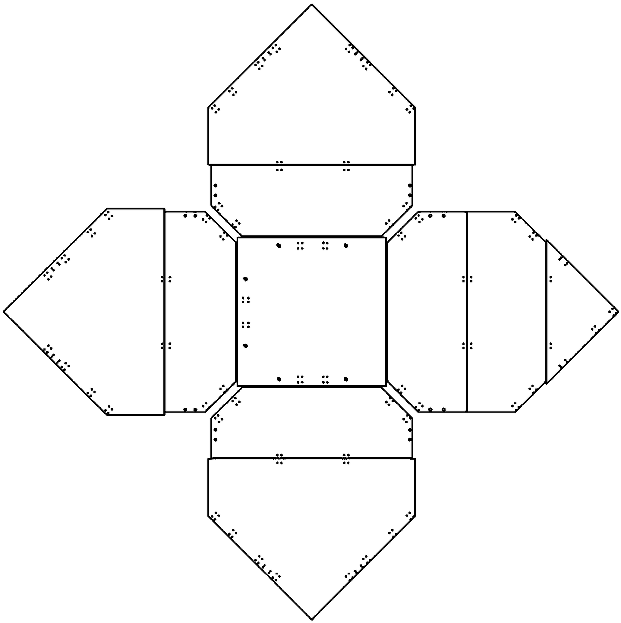
[0047] The preparation method of the cover plate is given below. In this method, each of the above-mentioned detachable units is prepared in the following manner, and after the preparation is completed, the final cover plate is connected according to the above connection method; the internal skeleton is used as a cross grid structure. illustrate. Specific preparation such as Figure 8 As shown, the steps are as follows:

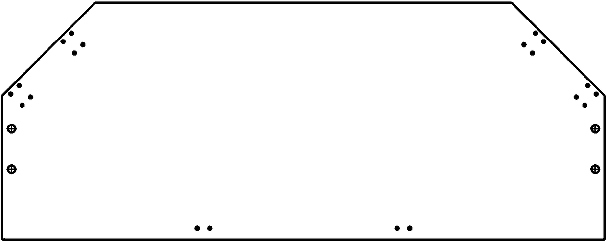
[0048] (1) Process the foam according to the design size and position of the actual foam core material and inner core, such as Figure 7 , Figure 5 As shown; according to the design drawings, for example, the foam at the position of the FRP pre-embedded block is in a disconnected state, and the thickness control at the intersection of the grid skeleton should be considered during the processing. Generally, the thickness of the skeleton skin is 1 to 1.5 times smaller than the design size;

[0049] (2) Build a skeleton forming mold composed of edge stoppe...

example 1

[0060] The metal mandrel, frame mold and pressure equalizing plate are made of Q235 steel. The shape of the product is a quadrilateral flat plate, and the overall size is 1200mm×1200mm×35mm.

[0061] The three sides of the product are simply supported, the center is loaded with a 500kg counterweight, and the load is maintained for 20 minutes. The deformation of the center is 3.7mm, and the deformation of the free side is 2.1mm.

example 2

[0063] The metal mandrel, frame mold and pressure equalizing plate are made of Q235 steel. The shape of the product is a pentagonal flat plate, and the overall size is 1600mm×1300mm×35mm.

[0064] The three sides of the product are simply supported, the center is loaded with a 500kg counterweight, and the load is maintained for 20 minutes. The deformation of the center is 3.7mm, and the deformation of the free side is 2.1mm.

[0065] The four sides of the product are simply supported, and the side in the middle of the two right angles is the free side. A 500kg counterweight is loaded at the center, and the load is maintained for 20 minutes. The deformation of the free side is 13.6mm.


PUM

PropertyMeasurementUnit
densityaaaaaaaaaa
elastic modulusaaaaaaaaaa
thicknessaaaaaaaaaa

Abstract

The invention discloses a composite-material core-level cover plate for a rocket, and a preparation method thereof. The cover plate comprises nine detachable units, wherein each detachable unit is a composite-material interlayer structure containing an inner framework; and one is a central quadrilateral unit and the other eight detachable units are divided into four groups, the two detachable units in each group are connected together through a hinge, the four sides of the central quadrilateral unit are lapped and fixed to one turned edge of the four groups of detachable units separately, theother sides of the four groups of detachable units are placed on a launching platform installation frame and fixed, and the whole outer edge outline is determined by an installation connector space where the cover plate is located. The invention puts forward for the first time that a light-weight foam interlayer structure containing the inner framework is applied to the core-level cover plate forthe rocket. The composite-material core-level cover plate has the advantages of being convenient to transport, simple to install, rapid to detach, and the like; and the disclosed preparation method has the advantages of ensuring the good forming quality of products, realizing integrated forming, and achieving low cost.

Description

technical field [0001] The invention relates to a rocket core-level cover plate and a preparation method thereof, belonging to the technical field of resin-based composite lightweight interlayer structure molding, and in particular to the molding of large-sized, internal skeleton-containing, foam interlayer, and combined assembly structures. Background technique [0002] In recent years, foam sandwich composite structures have been widely used in the fields of launch vehicles, aviation, wind turbine blades, sports equipment, medical equipment accessories, shipbuilding, train locomotives, etc., especially in developed countries such as the United States and Japan, and are widely used in high-tech Fields, mainly include: fairing, interstage section intermediate, heat shield and propeller nose cone of American Delta launch vehicle, fairing, interstage section and helicopter engine of Mitsubishi HII-A launch vehicle Body and blades, spherical frame and hat-shaped ribs of Airbus ...

Claims


Application Information

Patent Timeline
Patent Type & Authority Applications(China)
IPC IPC(8): B29C70/36B29C70/54B29C70/70B29L31/30
CPCB29C70/36B29C70/545B29C70/70B29L2031/3097
Inventor 唐占文史汉桥雷琴黎定仕王爱春何析峻
Owner AEROSPACE RES INST OF MATERIAL & PROCESSING TECH
Why Eureka
Try Eureka