
Improved sludge treatment system

Through the three-stage transmission surface system and multi-dimensional mixing design, the problems of low sludge drying efficiency and complex structure are solved, and a sludge treatment system with efficient drying and simplified structure is realized.

Inactive Publication Date: 2018-09-04
卢江
View PDF7 Cites 0 Cited by
  • Summary
  • Abstract
  • Description
  • Claims
  • Application Information

AI Technical Summary

Problems solved by technology

[0006] Therefore, the technical problem to be solved by the present invention is to overcome the defects of low drying efficiency, poor drying effect and complex structure of the drying system in the treatment of solid-liquid mixture (such as sludge) in the prior art, thereby providing a method that can improve drying efficiency. , Sludge treatment system with simple structure and improved drying effect

Method used


Image

  • Improved sludge treatment system
  • Improved sludge treatment system
  • Improved sludge treatment system

Examples


Embodiment 1

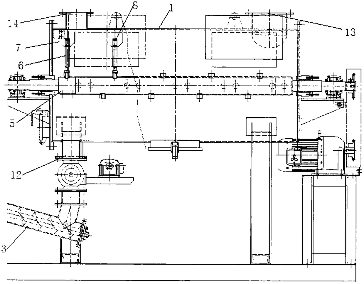
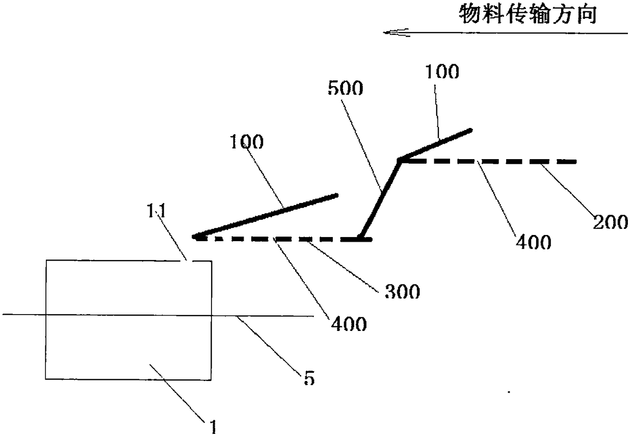
[0040] Such as Figure 1-3 As shown, this embodiment provides a sludge treatment system, including

[0041] The transmission device has a three-level transmission surface, the first-level transmission surface is located above the side of the second-level transmission surface, the second-level transmission surface is located above the side of the third-level transmission surface, the first-level transmission surface 200 and the second-level transmission surface Between the planes 300, and between the second-level transmission plane 300 and the third-level transmission plane are respectively connected through transition devices 500, and the height between the first-level transmission plane 200 and the second-level transmission plane 300 is smaller than that of the second-level transmission plane 300 and the height between the third-stage transmission surface, the transmission device can transport the solid-liquid mixed sludge from the head end of the first-stage transmission sur...


PUM

PropertyMeasurementUnit
distanceaaaaaaaaaa

Abstract

The invention relates to a sludge treatment system. The sludge treatment system comprises a transmission device, a water-removing structure and a drying device; the drying device comprises a furnace body, a feeding device, a material receiving device, a wind supply device and a stirring device; the feeding device is used for adding materials into the furnace body; the material receiving device isused for collecting the dried materials in the furnace body; and the wind supply device is used for stirring and pulverizing the materials. When the materials are dried, hot gas is introduced into a cavity of the furnace body through a first gas inlet, and a second rotating shaft rotates to drive a stirring assembly on the second rotating shaft to continuously stir the materials along the radial direction and the axial direction of the second rotating shaft, so that the materials can roll in the furnace body along the axial direction and the radial direction of the second rotating shaft, the stirred time of the materials is increased and the heat convection area of the materials and the hot gas is enlarged. In addition, the stirring assembly can pulverize the materials to form the small-granule materials, so that the heat convection area of the materials and the hot gas is further enlarged, and the drying efficiency and the drying effect of the materials are improved.

Description

technical field [0001] The invention relates to the technical field of sludge treatment, in particular to an improved sludge treatment system. Background technique [0002] Sludge is the product of the sewage treatment process, which contains a large amount of organic matter, heavy metals and molds, etc. If no follow-up treatment is added, it will cause serious pollution to the environment. Therefore, it is often necessary to concentrate and dehydrate the sludge, but after this treatment The moisture content of the final sludge is usually above 70%, and the sludge needs to be further dried. [0003] In the prior art, the drying system used for sludge drying is mostly structured as the drying system disclosed in the Chinese patent document CN201058838Y, including a furnace body, a feeder connected to the feed port of the furnace body, and an air outlet of the furnace body. Connected spray tower. Among them, the furnace body includes a transmission shaft arranged in the furn...

Claims


Application Information

Patent Timeline
Patent Type & Authority Applications(China)
IPC IPC(8): C02F11/12
CPCC02F11/12C02F11/121C02F2201/002C02F2303/26
Inventor 王海龙
Owner 卢江
Learn More