Water spraying loom battening shaft waterproof ring

A technology of water-jet looms and waterproof rings, which is applied in looms, textiles, textiles and papermaking, etc., can solve the problems of reducing the waterproof effect, reducing the service life of the beating shaft, and reducing the weaving efficiency of water-jet looms, so as to improve Maintenance and replacement efficiency, and the effect of improving the waterproof effect

Pending Publication Date: 2018-09-04
SHANDONG RIFA TEXTILE MACHINERY
View PDF13 Cites 2 Cited by
  • Summary
  • Abstract
  • Description
  • Claims
  • Application Information

AI Technical Summary

Problems solved by technology

Once the bearing pad support is used, the waterproof problem of the bearing pad seat section of the beating shaft will be highlighted, because the beating shaft of the water jet loom works in a water bath state, and the shaft section combining the bearing pad and the shaft cannot be done. For surface anti-corrosion treatment such as paint, if the shaft section at the bearing bush gets water, the shaft will corrode and rust soon, and at the same time, the bearing bush will wear out and fail, and the whole beating shaft will need to be scrapped
[0003] The waterproof ring of the existing water-jet loom beat-up shaft bearing shell seat section mostly adopts a full-circle rubber ring labyrinth seal structure, which has the following disadvantages: 1. The seal ring rotates with the beat-up shaft, and the The bearing seat cannot fit tightly, and there will be a small amount of water ingress; 2. The rubber material has an aging cycle. Once it is aged, it will harden and deform, which will significantly reduce the waterproof effect. It is necessary to replace a new waterproof ring. The replacement process is complicated and requires Remove the whole beat-up shaft
waste of time, labor
These disadvantages will not only reduce the service life of the beating shaft, but also reduce the weaving efficiency of the water jet loom due to the long maintenance time

Method used


Image

  • Water spraying loom battening shaft waterproof ring
  • Water spraying loom battening shaft waterproof ring
  • Water spraying loom battening shaft waterproof ring

Examples


Embodiment Construction

[0019] In order to better understand the present invention, the implementation manner of the present invention will be explained in detail below in conjunction with the accompanying drawings.

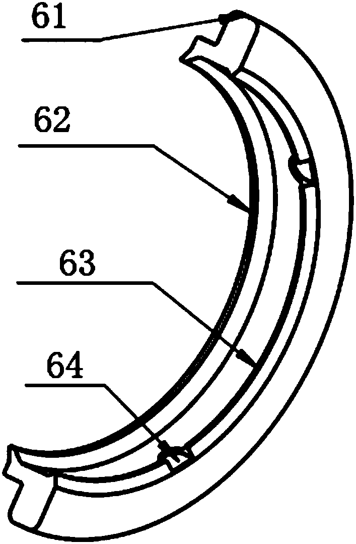
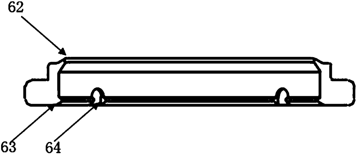
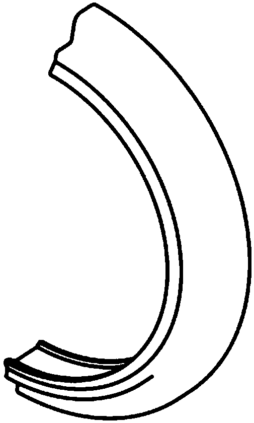
[0020] Such as figure 1 As for Figure 5 As shown, a water-jet loom beat-up shaft waterproof ring, the components involved include: a beat-up shaft 1, a bearing pad seat support 2, a bearing pad seat fixing screw 3, a bearing pad seat 4, a bearing pad 5, a waterproof ring 6, and a bearing pad Seat connection screw 7, the bearing pad support 1 is fixed on the frame through screw connection, the bearing pad seat 4 is connected to the bearing pad seat support 1 through the bearing pad seat fixing screw 3, and is kept fixed with it after adjusting the position, the bearing pad 5 is installed on the bearing bush seat 4 and kept fixed with it. The beat-up shaft 1 passes through the space in the middle of the bearing bush 5, keeps coaxial with it, and swings along the axis within a certain an...


PUM


Abstract

The invention relates to a water spraying loom battening shaft waterproof ring. The ring is used in cooperation with a battening shaft, a bearing shell seat and a bearing shell; the ring has the advantages of simple structure and low manufacturing cost, components are of split semi-circular structures, and are mounted on the bearing hell seat, and the ring is convenient to maintain and disassemble; an outer ring main frame tightly fits a bearing shell seat mounting groove, a waterproof ring does not rotate with a battening shaft, and is static relative to the bearing shell seat to prevent water from entering the joint between the waterproof ring and the bearing shell seat, an inner ring is provided with oil sealing lips on both sides and an intermediate oil groove to form triple waterproofprotection, and the waterproof ring is highly waterproof; at least one opening is formed in the inner side oil sealing lips to provide convenience for the extrusion of inner bearing shell lubricatinggrease in a substantially uniform state, the lubrication of a bearing shell structure is not affected, and the waterproof efficiency is improved. The waterproof ring enables the battening shaft bearing shell structure to be used normally for a long time in a water bath environment, and is easy to maintain.

Description

technical field [0001] The invention relates to the technical field of textile machinery, in particular to a water-jet loom beat-up shaft waterproof ring. Background technique [0002] In the current water-jet loom market, more and more water-jet looms use solid beating shafts supported by bearing pads to replace the old hollow barrel beating-up shafts without bearing pads to increase the beating strength. To meet the weaving needs of more new chemical fiber fabrics. Once the bearing pad support is used, the waterproof problem of the bearing pad seat section of the beating shaft will be highlighted, because the beating shaft of the water jet loom works in a water bath state, and the shaft section combining the bearing pad and the shaft cannot be done. For surface anti-corrosion treatment such as paint, if the shaft section at the bearing pad is infiltrated with water, the shaft will corrode and rust soon, and at the same time, the bearing pad will wear and fail, and the ent...

Claims


Application Information

Patent Timeline
Patent Type & Authority Applications(China)
IPC IPC(8): D03D49/60
CPCD03D49/60
Inventor 许泽兵王业华
Owner SHANDONG RIFA TEXTILE MACHINERY
Why Eureka
Try Eureka