Rock breaking device

A technology of rock breaking device and traveling device, which is applied to earth moving machines/shovels, earthwork drilling and cutting machines, etc., can solve the problems of large momentum loss, increase the thrust of the oil cylinder, influence the torque, etc. Reduced force, improved rigidity transmission capability, and large torque adjustment range

Active Publication Date: 2018-09-04
凌夕珈
View PDF10 Cites 2 Cited by
  • Summary
  • Abstract
  • Description
  • Claims
  • Application Information

AI Technical Summary

Problems solved by technology

[0009] The ratio of the vertical distance from the axis of the ripper cylinder 5 to the seventh hinge shaft 63 to the distance from the seventh hinge shaft 63 to the lower end 72 of the ripper is the first lever ratio, and the first lever can have a larger ratio. The ratio of the distance to the first hinge axis 34 and the distance from the first hinge axis 34 to the lower end 72 of the ripper is the second leverage ratio. When the second lever ratio remains unchanged, the first lever ratio is large, and the loss of momentum in transmission Smaller, due to the structural characteristics of the existing rock-breaking device, the ratio of the first lever is small, resulting in a large loss of momentum during transmission
[0010] The total weight of the rock-breaking device is limited, and its weight cannot exceed the bearing capacity of the excavator. The lateral excavation force can be changed by changing the moment of the arm, and the thrust of the cylinder can be increased by changing the cylinder diameter of the stick cylinder and the ripper cylinder. It can be controlled within the range that the excavator can bear, so it is limited to improve the rock-breaking ability by increasing the weight of the boom and forearm and changing the moment of the forearm.
[0011] Due to the small proportion of the weight of the ripper in the weight of the rock-breaking device, the structure of the ripper is unreasonable, and the relationship between the ripper cylinder, the ripper and the forearm structure is unreasonable, resulting in high energy consumption and poor rock-breaking effect.
[0012] The application number is 201710438688.5. The forearm of the rock breaking device and the ripper have an integrated structure. Its purpose is to avoid the blockage of the oil cylinder, increase the digging depth, and reduce the connection relationship, which is conducive to the rigid transmission of gravity to the tooth tip of the ripper. However, This will seriously reduce its flexibility. In the actual mining operation, the flexibility will seriously affect the rock entry angle of the ripper. The excavation force and the rock entry angle are the most important factors affecting the rock breaking effect, so the use effect of this technology is not good. Good, resulting in less usage at the moment
[0013] In short, the existing rock-breaking device has the unreasonable ratio of the upper volume of the ripper to the lower volume, which affects the setting of the moment. Problems of poor rock-entry angle, high energy consumption and poor rock-breaking effect of earthenware

Method used


Image

  • Rock breaking device
  • Rock breaking device
  • Rock breaking device

Examples


Embodiment 1

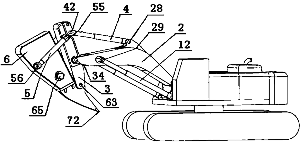
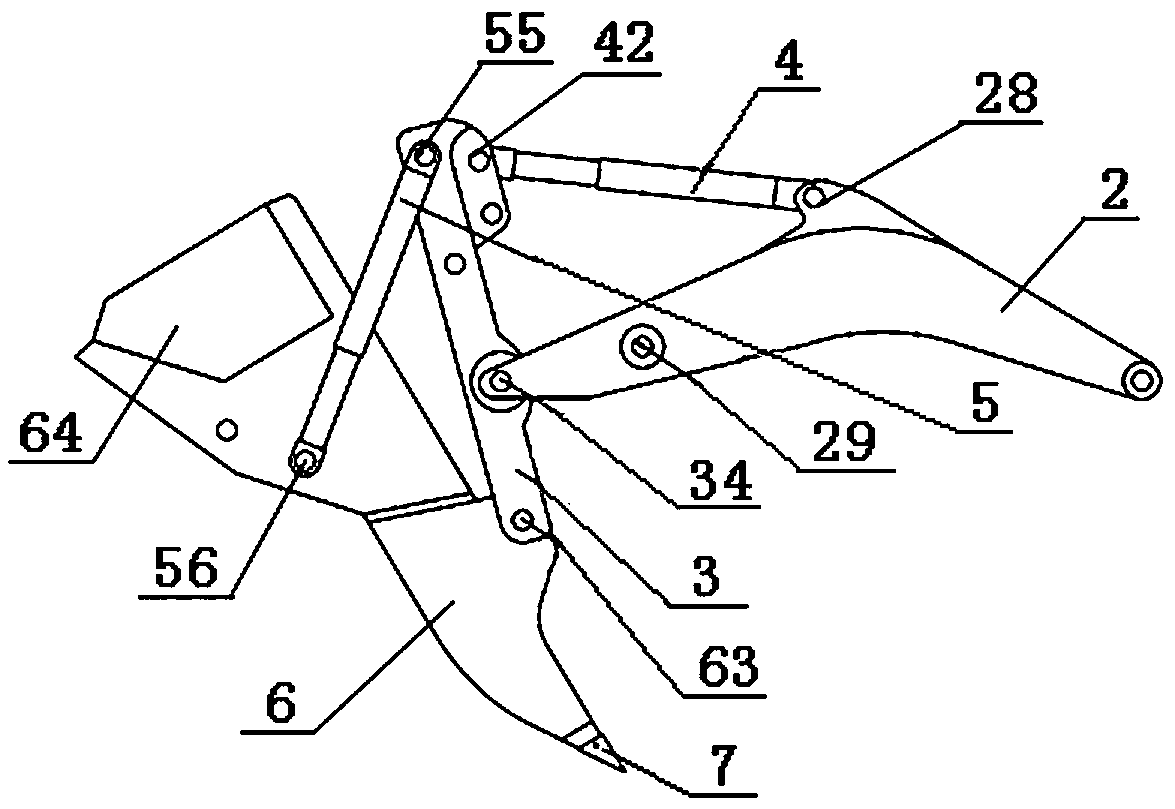
[0053] A rock-breaking device mounted on an excavator, comprising a large arm 2, a small arm 3 ripper 6, a stick cylinder 4, a ripper cylinder 5, and bucket teeth 7. The excavator has an upper body and a lower traveling device, The upper vehicle body is rotatably connected to the lower traveling device. One end of the boom 2 is hinged to the upper body of the excavator, and the other end is hinged to the small arm 3 through the first hinge shaft 34. One end of the boom cylinder is hinged to the upper vehicle body, and the other end is hinged to the The boom is hinged through the second hinge shaft 29, one end of the arm cylinder 4 is hinged with the upper middle of the boom through the third hinge shaft 28, and the other end is hinged with the upper end of the small arm 3 through the fourth hinge shaft 42, and the upper end of the small arm 3 is connected by The fifth hinge shaft 55 is hinged with one end of the ripper cylinder 5, the other end of the ripper cylinder 5 is hinge...

Embodiment 2

[0064] The weight of the ripper is 10.37 tons, and the weight of the ripper is 61% of the total weight of the rock breaking device.

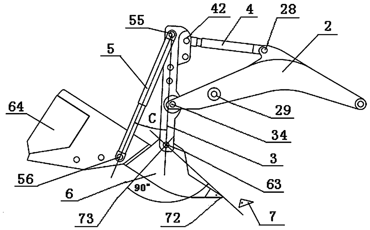
[0065] There are 2 positions for the 4th hinge axis, 3 positions for the 5th hinge axis, and 3 positions for the 6th hinge axis.

[0066] Line 73 divides the ripper into upper and lower parts. After calculation, the weight of the lower part is 1.07 tons and the volume is 0.137 cubic meters. The weight of the upper part is 9.3 tons and the volume is 1.19 cubic meters. The weight of the upper part is 8.7 times the weight of the lower part.

[0067] The jib weighs 2 tons and has a volume of 0.52 cubic meters.

[0068] Ripper 6 does not have a hollow cavity.

[0069] When the ripper cylinder 5 is installed at the minimum angle of the included angle C, when the ripper cylinder is fully retracted, the included angle C is 24 degrees, and the vertical distance from the axis of the ripper cylinder 5 to the hinge shaft 63 is 1040 mm, and the hinge shaft 63...

Embodiment 3

[0077] The weight of the ripper is 14.45 tons, and the weight of the ripper is 85% of the total weight of the rock breaking device.

[0078] There are 2 positions on the 4th hinge axis, 3 positions on the 5th hinge axis, 4 positions on the 6th hinge axis, and 1 position on the 7th hinge axis.

[0079] Line 73 divides the ripper into upper and lower parts, the lower part weighs 0.9 tons and has a volume of 0.115 cubic meters, and the upper part weighs 13.55 tons and has a volume of 1.74 cubic meters, and the weight of the upper part is 15 times the weight of the lower part.

[0080] When the ripper cylinder 5 is installed at the maximum angle of the included angle C, when the ripper cylinder is fully retracted, the included angle C is 143 degrees, and the vertical distance from the axis of the ripper cylinder 5 to the hinge shaft 63 is 892 mm, and the hinge shaft 63 to the lower end The distance of 72 is 1775 mm, the ratio of power arm to resistance arm is 0.5, the maximum dist...


PUM


Abstract

The invention relates to a rock breaking device carried to an excavator, and the problems that an existing device scarifier is poor in rock entering angle, energy consumption is high, and the rock breaking effect is poor are solved. One end of a bucket rod cylinder is hinged to the upper edge of the middle portion of a big arm, and the other end of the bucket rod cylinder is hinged to the upper end of a small arm. The upper end of the small arm and one end of a scarifier oil cylinder are hinged, the other end of the scarifier oil cylinder is hinged to the upper end of the scarifier, the lowerend of the scarifier is connected with bucket teeth, and the ratio of the distance between a fourth hinge shaft and a first hinge shaft to the distance between the first hinge shaft and a seventh hinge shaft is larger than 0.8, the length of an upper part of the scarifier is larger than the distance between a fourth hinge shaft and the first hinge shaft, and when the fourth hinge shaft has multiple installing positions, the shortest distance serves as the criterion for the distances between the fourth hinge shaft and the first hinge shaft, and the length of the upper part of the scarifier is larger than the distance between the first hinge shaft and the seventh hinge shaft, and when the first hinge shaft has multiple installing positions, the shortest distance serves as the criterion for the distances between the first hinge shaft and the seventh hinge shaft, the total length of the scarifier is larger than the distance between the fourth hinge shaft and the seventh hinge shaft, and when the fourth hinge shaft has multiple installing positions, the shortest distance serves as the criterion for the distances between the fourth hinge shaft and the seventh hinge shaft.

Description

technical field [0001] The present invention relates to a rock breaking device mounted on an excavator. Background technique [0002] In rock formation mining construction operations, for rock formations that are not very hard, the construction method of carrying a ripper on an excavator is widely used because of its good construction effect. For this construction method, the prior art works on the boom, forearm and ripper Many optimizations and improvements have been made to improve the use effect. [0003] Here the device made up of boom, forearm, ripper and oil cylinder is called rock breaking device. The existing rock-breaking device improves the rock-breaking ability by changing the torque of the forearm and increasing the weight of the boom and forearm. The ratio of the distance between the connecting point of the arm and the connecting point of the small arm and the large arm to the connecting point of the small arm and the ripper is 0.4-0.8. In the actual use of t...

Claims


Application Information

Patent Timeline
Patent Type & Authority Applications(China)
IPC IPC(8): E02F3/38E02F5/32E21C27/30
CPCE21C27/30E02F3/301E02F3/32E02F3/38E02F5/32E02F5/326E02F3/966E02F9/22
Inventor 凌夕珈
Owner 凌夕珈
Why Eureka
Try Eureka