Slope drainage trench design method and application and drainage trench

A design method and technology of drainage ditches, applied in waterway systems, water supply devices, sewer pipe systems, etc., can solve problems such as unreasonable slopes, drainage groove sections, and failure to reach, so as to improve governance, avoid material waste, increase The effect of stability

Active Publication Date: 2018-09-04
陕西秦草生态环境科技有限公司 +1
View PDF4 Cites 1 Cited by
  • Summary
  • Abstract
  • Description
  • Claims
  • Application Information

AI Technical Summary

Problems solved by technology

[0003] Because in the traditional method, only the stability checking and analysis of the slope angle is carried out, and the construction is carried out only based on experience and estimation, so in the actual slope treatment, there are often too large or too small sub-slopes, and the section and slope of the drainage ditch are not correct. Reasonable, so that the construction under construction or the completed project will experience severe erosion and collapse after a certain amount of rainfall, and the drainage ditch will be in vain and will not play its due role

Method used


Image

  • Slope drainage trench design method and application and drainage trench
  • Slope drainage trench design method and application and drainage trench
  • Slope drainage trench design method and application and drainage trench

Examples


Embodiment 1

[0029] This embodiment provides a design method for a slope drainage ditch, which includes:

[0030] S1. The position of the preset drainage groove, the drainage groove includes a horizontal drainage groove and a vertical drainage groove, and the horizontal drainage groove and the vertical drainage groove are connected.

[0031] Wherein, in a preferred embodiment of the present invention, the basis for the preset location of the drainage ditch is the rainfall in the area where the slope is located, the soil quality of the area where the slope is located, and the slope angle of the slope. Wherein, the rainfall in the area where the slope is located can be obtained by querying existing data, and the soil quality and slope angle of the area where the slope is located are measured according to existing methods and equipment, and will not be described in detail here.

[0032] S2. (1) Obtain the calculated flow rate due to rainfall accumulation on the control slope of the lateral dr...

Embodiment 2

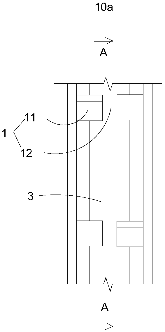
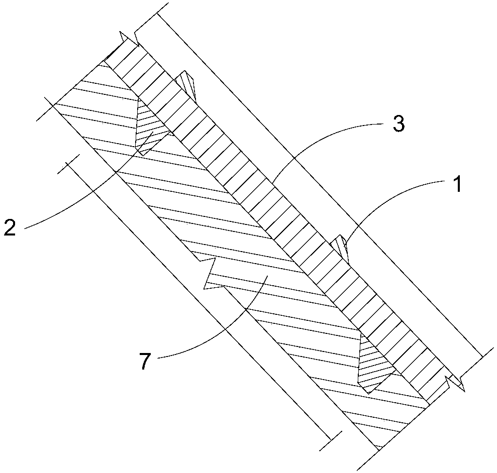
[0084] see figure 1 as well as figure 2 , the present invention also provides a drainage ditch (not shown in the figure), which is designed according to the design method of the above-mentioned slope drainage ditch. The drainage groove includes a vertical drainage groove 10a arranged vertically. The vertical drainage groove 10a is arranged on the slope 7 with the same slope as the slope 7. The vertical drainage groove 10a is provided with a water retaining ridge 1 and an anti-slip ridge 2 .

[0085] The water-retaining sill 1 is arranged on the bottom wall 3 of the longitudinal drainage groove 10a along the longitudinal direction of the longitudinal drainage groove 10a. The cross-section of the water-retaining sill 1 is trapezoidal. The width of the side of the water retaining sill 1 close to the bottom wall 3 of the longitudinal drainage groove 10a is greater than the width of the side of the water retaining sill 1 away from the bottom wall 3 of the longitudinal drainage gr...


PUM


Abstract

The invention relates to the field of civil engineering design and relates to a slope drainage trench design method and application and a drainage trench. The design method includes: presetting a transverse drainage trench position and a longitudinal drainage trench position, preliminarily planning a slope dividing scheme, and performing drainage trench section design according to transverse and longitudinal drainage trench control areas; if a result is unreasonable according to computation, re-planning a slope dividing scheme until qualification is achieved, and then constructing. By adoptionof the method, reasonability in slope dividing and drainage trench design can be realized, and excellent drainage effects are achieved; in addition, stability of the drainage trench is improved, engineering projection service life is prolonged, and maintenance cost is reduced; further, a wide application range is realized, and the method can be applied to design of mining area slopes, railway slopes and highway slopes.

Description

technical field [0001] The invention relates to the field of civil engineering design, in particular to a design method and application of a drainage ditch on a slope, and the drainage ditch. Background technique [0002] In the traditional slope treatment, in addition to grading, that is, cutting the steeper slope with an excavator to slow down the slope, a number of bridleways are built in the middle of the slope, and the slope is treated through bridleways and longitudinal drainage grooves. Split, that is, divide the slope. The large-area slope is divided into several smaller-area slopes, so that the flood caused by rainfall can be effectively controlled. That is, the horizontal drainage ditch built on the road with the function of collecting rainwater and draining water is connected with the vertical drainage ditch built along the slope. Let the rainwater on the slope flow down the slope, collect in the horizontal drainage ditch on the horseway, then flow to the longit...

Claims


Application Information

Patent Timeline
Patent Type & Authority Applications(China)
IPC IPC(8): E03F3/04
CPCE03F3/046
Inventor 高鸿永高旭日高科
Owner 陕西秦草生态环境科技有限公司
Why Eureka
Try Eureka